Author: Rachel Sousa

  • Water-Cement Ratio: Why It Matters More Than Anything Else

    Water-Cement Ratio: Why It Matters More Than Anything Else

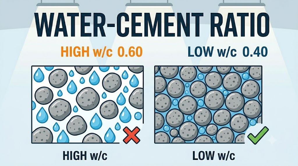
    The water-cement (w/c) ratio — the weight of water divided by the weight of cement in a mix — controls concrete strength more directly than any other single variable. Lower w/c ratio means higher strength, lower permeability, and longer service life. Raise it from 0.40 to 0.60 and compressive strength drops by roughly 40%. No amount of extra cement recovers that loss.

    How the water-cement ratio determines strength

    The relationship between w/c ratio and strength follows Abrams’ Law, established in 1919: for a given set of materials and curing conditions, compressive strength is an inverse function of the w/c ratio. The relationship is approximately:

    f’c = A / B^(w/c)

    where A and B are empirical constants derived from trial mixes with your specific materials. In practice, reducing w/c from 0.60 to 0.45 increases 28-day compressive strength by approximately 45–55% for standard OPC mixes. This is the lever that matters most in concrete mix design.

    Use the water-cement ratio calculator to determine the correct w/c ratio for your target strength, or to calculate what strength your current mix is likely to produce.

    Maximum w/c ratios are specified by codes for specific exposure conditions. ACI 318 limits w/c to 0.40 for concrete exposed to seawater or deicers, 0.45 for moderate sulphate exposure, and 0.50 for general water exposure. IS 456 limits it to 0.40–0.55 depending on exposure class. Eurocode limits range from 0.45 (XS3 marine splash) to 0.60 (XC1 dry internal).

    W/C ratio limits by strength class and exposure

    Target strengthMax w/c ratioMin cement (kg/m³)Typical exposure
    M15 / 2,175 PSI0.60250Protected interior fill
    M20 / 2,900 PSI0.55300Mild — RC slabs, beams
    M25 / 3,625 PSI0.50320Moderate — driveways, foundations
    M30 / 4,350 PSI0.45340Severe — bridges, retaining walls
    M35 / 5,075 PSI0.40360Very severe — marine, deicers
    M40 / 5,800 PSI0.35380Extreme — offshore, prestressed

    Minimum cement contents exist because a low w/c ratio at very low cement content produces a mix that is too dry to compact properly. At w/c = 0.35 with 380 kg/m³ cement, the mix contains only 133 litres / 35 US gallons of water per m³ — workability must be achieved through superplasticiser, not additional water.

    The workability problem: why contractors add too much water

    Every 10 litres / 2.6 US gallons of extra water per m³ of concrete raises the w/c ratio by approximately 0.03–0.05 and reduces 28-day compressive strength by 3–5 MPa (435–725 PSI). A slump increase from 75 mm to 175 mm (3 in to 7 in), achieved by adding water at the truck, can take M25 concrete below M20 performance.

    The correct approach is to achieve required workability through chemical admixtures — plasticisers, superplasticisers (HRWR), or mid-range water reducers — not additional water. Modern superplasticisers reduce water demand by 20–30% at the same slump, or achieve 200 mm slump at the same w/c ratio. The concrete admixture dosage calculator converts the manufacturer’s recommended dosage percentage into actual litres or kg per m³ for your batch volume.

    On-site water additions are particularly damaging because they are not measured. A ready-mix truck driver adding 50 litres / 13 gallons to a 6 m³ delivery raises the w/c by 0.06–0.10 across the entire load — enough to move from a structurally acceptable mix to a non-compliant one. Most concrete delivery dockets specify the maximum allowable water addition; anything beyond that voids the strength guarantee.

    Common mistakes involving water-cement ratio

    Adding water to the truck at the pour. This is the most common cause of understrength concrete on residential and small commercial jobs. A m³ of M25 concrete leaves the plant at w/c = 0.47. Adding 40 L at the site takes it to approximately 0.54 — equivalent to M20. The concrete sets, looks fine, and fails a core test months later. If the concrete is too stiff to work, specify a higher-slump mix at the plant, or add a mid-range water reducer at the plant, not water on site.

    Not accounting for aggregate moisture in the w/c ratio. Aggregate in most stockpiles carries 1–3% absorbed moisture plus surface moisture. If batch water is calculated assuming bone-dry aggregate, the effective w/c ratio is higher than designed. Aggregate moisture testing (ASTM C566 / BS 812-109) should be done on each stockpile used for structural mixes above M25.

    Using w/c ratio to specify instead of minimum cement content. A low w/c ratio at very low cement content (say 0.40 with 200 kg/m³ cement) produces 80 litres of water per m³ — too dry to compact without heavy vibration. Always specify both maximum w/c ratio and minimum cement content together. For M30 and above, the minimum cement content is the more restrictive constraint in most cases.

    Confusing w/c with water-to-binder (w/b) ratio. When supplementary cementitious materials (SCMs) — fly ash, GGBS, silica fume — replace part of the cement, the water-to-binder ratio divides water by total binder (cement + SCM). Codes typically specify w/b for durability. A mix with 300 kg OPC and 100 kg fly ash at 160 kg water has w/c = 0.53 but w/b = 0.40. Check whether the specification means w/c or w/b before ordering.

    Related calculators you might need

    The water-cement ratio is the starting point for mix design, not the end point. Once you have your target w/c ratio, the cement quantity calculator converts it into bags per m³ using your specified cement content. For projects above M25 where admixtures are involved, the concrete admixture dosage calculator prevents under-dosing or over-dosing plasticisers. If you are trying to verify whether an existing mix meets a structural specification, the concrete compressive strength converter converts core test results between PSI, MPa, and N/mm² for direct comparison against the spec. And the concrete mix ratio calculator ties all variables together into a full batch design.

    Frequently asked questions

    What is a good water-cement ratio for concrete?

    For standard reinforced concrete slabs, beams, and columns, the target is 0.45–0.50. Below 0.40, workability requires a superplasticiser. Above 0.55, durability starts to degrade — permeability increases and chloride ingress accelerates in exposed structures. For residential flatwork not exposed to deicers or seawater, 0.50–0.55 is acceptable. For driveways, foundations, or any element exposed to moisture cycling, 0.45–0.50 is the right range.

    How does water-cement ratio affect concrete strength?

    Lowering w/c ratio from 0.60 to 0.40 roughly doubles 28-day compressive strength — from around 20 MPa to 40 MPa for standard OPC. The relationship follows Abrams’ Law: every 0.05 reduction in w/c ratio adds approximately 3–5 MPa (435–725 PSI) depending on the cement type and aggregate characteristics. The gain is not linear at very low ratios (below 0.35) because incomplete hydration limits strength.

    What happens if water-cement ratio is too low?

    Below about w/c = 0.38, there is insufficient water to fully hydrate all the cement particles. This leaves unreacted cement that provides no strength benefit — a waste of material. More importantly, very low w/c mixes are extremely stiff and will not consolidate properly without mechanical vibration or high-range water reducers. Poor compaction at low w/c creates voids that reduce strength and durability more than a slightly higher w/c ratio would.

    Can I calculate the w/c ratio from a ready-mix docket?

    Ready-mix dockets list total water added at the plant, mix design water, and sometimes aggregate moisture correction. To calculate w/c: divide total mix water (litres) by total cement content (kg). If the docket shows 160 L of water and 350 kg of cement, w/c = 160/350 = 0.457. Note that dockets may show plant-added water only — aggregate moisture adds to this. Ask the plant for the full mix design sheet if you need a verified w/c ratio for a structural record.

    Does w/c ratio affect concrete curing time?

    Lower w/c mixes hydrate faster because the cement-to-water proximity is greater, but they are also more sensitive to early drying. At w/c = 0.40, if the surface dries prematurely, hydration stops in the outer zone while the core continues — producing a weak, permeable surface layer. Lower w/c mixes require longer, more rigorous curing — minimum 7 days of continuous moisture for M30+, compared to 3–5 days for M20.

  • What Concrete Admixtures Actually Do (And When to Use Them)

    What Concrete Admixtures Actually Do (And When to Use Them)

    Concrete admixtures are chemical or mineral materials added to a mix — either at the plant or on site — to modify the properties of fresh or hardened concrete. The five categories used on most construction projects are water reducers, retarders, accelerators, air-entraining agents, and superplasticisers (HRWR). Each does one primary job. Using the wrong one, or using the right one at the wrong dosage, reliably causes problems.

    The five main admixture types and their mechanism

    Water reducers (plasticisers) work by dispersing cement particles through electrostatic repulsion. When cement hydrates, particles tend to flocculate — clumping together and trapping water in the floc structure. A plasticiser coats the cement surface and forces the particles apart, releasing that trapped water for workability. The result: 5–15% reduction in water demand at the same slump, or a higher slump at the same w/c ratio. This is how you improve workability without touching the water-cement ratio.

    High-range water reducers (superplasticisers / HRWR) use a longer polymer chain — typically polycarboxylate ether (PCE) — that provides both steric and electrostatic dispersion. They deliver 20–40% water reduction or will fluidise a stiff mix to self-compacting concrete without affecting strength. Superplasticisers are the enabling technology for M35+ concrete: they allow low w/c ratios (0.30–0.40) to remain pourable. Dosage is typically 0.5–2.0% by weight of cement.

    Retarders slow the rate of cement hydration by interfering with C3S and C3A reaction kinetics — the early-strength compounds in clinker. They extend working time from the standard 1–2 hours to 4–8 hours, or longer. Essential for hot-weather concreting above 30°C / 86°F, long-haul deliveries, large pours where all concrete must remain workable until finishing, or architectural concrete where cold joints cannot be tolerated.

    Accelerators speed up cement hydration — shortening the time to initial set and accelerating early strength gain. Calcium chloride (CaCl₂) was the standard, but it corrodes steel reinforcement and is now prohibited in reinforced concrete. Modern non-chloride accelerators (typically calcium nitrite or sodium thiocyanate formulations) are used instead. They are standard for cold-weather concreting below 5°C / 41°F, for pre-cast production where early stripping is economically important, and for repair mortars that need to carry load quickly.

    Air-entraining agents (AEA) generate a stable network of microscopic air bubbles — 0.05–1.25 mm / 0.002–0.05 in diameter — distributed uniformly through the paste. The bubbles act as pressure-relief chambers during freeze-thaw cycling: when pore water freezes and expands, ice crystal growth pressure is accommodated in the adjacent voids rather than cracking the paste. Correctly air-entrained concrete (3–6% air by volume) can withstand 300+ freeze-thaw cycles without scaling; the same mix without AEA may fail in 30.

    Use the concrete admixture dosage calculator to convert the manufacturer’s recommended percentage dosage into actual ml or kg per m³ for your batch volume. Manufacturer specifications are always expressed as a percentage of cement weight — the calculator does that conversion for any batch size.

    Admixture comparison: type, dosage, and when to specify

    Admixture typeTypical dosage (% by cement wt)Primary benefitWhen to use
    Plasticiser (WR)0.2–0.5%5–15% water reductionStandard RC mixes wanting better workability without extra water
    Superplasticiser (HRWR)0.5–2.0%20–40% water reductionM30+, SCC, low w/c structural mixes
    Retarder0.1–0.5%2–6 hr extended workabilityHot weather, long hauls, large monolithic pours
    Accelerator (non-Cl)1.0–3.0%Early strength up 30–50%Cold weather, early stripping, emergency repairs
    Air-entraining agent0.005–0.05%3–6% air entrainmentAny exposed flatwork in freeze-thaw climates
    Crystalline waterproofer0.8–1.5%Self-sealing capillary porosityWater-retaining structures, basement walls
    Shrinkage reducer0.5–1.5%Drying shrinkage down 25–50%Industrial floors, slabs with crack sensitivity
    Corrosion inhibitor1.0–3.0%Delays chloride attack on rebarMarine structures, bridge decks, car parks

    How admixtures interact with your mix design

    Admixtures do not fix a poorly designed mix — they optimise a correctly designed one. A superplasticiser cannot compensate for aggregate that is too coarse, a cement content that is too low, or a batch that was mixed without adequate water to start. The dosage must match the cement content and type: PCE superplasticisers are sensitive to cement alkali content and C3A levels. A product that works perfectly with a CEM I 52.5R cement may be incompatible with a GGBS blend, causing flash set or loss of workability. Always request a compatibility trial from your admixture supplier before specifying a new combination.

    Multiple admixtures can be combined, but must be dispensed separately into the mixer — never pre-blended together. Mixing a retarder and an accelerator in the dispenser hose will cause instant precipitation. The standard sequence is: aggregate, part water, cement, plasticiser, remaining water. Air-entraining agents are added with the initial water charge.

    Dosage verification is critical. The concrete air entrainment calculator determines the AEA dosage required to hit a target air percentage based on your aggregate size and cement content — because the same dosage rate produces different air contents across different mixes.

    Common mistakes when using admixtures

    Adding superplasticiser directly to a stiff truck. Pouring neat HRWR onto stiff concrete at the delivery point produces an uneven dosage — some areas get the full hit of plasticiser, others get none. This creates variable workability through the load and can leave pockets of unexpectedly fluid concrete that segregate during vibration. Superplasticiser should be added at the plant with the mix water, with at least 60 seconds of high-speed mixing to achieve uniform dispersion.

    Using calcium chloride accelerator in reinforced concrete. CaCl₂ is cheap and effective, but chloride ions penetrate to rebar depth and initiate electrochemical corrosion. BS 8500 prohibits calcium chloride in all concrete containing embedded metal; ACI 318 limits it to 0.06% by weight of cement, which is effectively a prohibition in any reinforced element. Using it in a reinforced slab to get early strip strength will cause rebar corrosion within 5–15 years in most climates. Use a calcium nitrite-based accelerator instead.

    Under-dosing air-entraining agent for aggregate size. The required AEA dosage increases as aggregate maximum size decreases — more surface area per unit volume means more air bubble nucleation sites are needed for the same entrained air percentage. For 20 mm / 0.75 in aggregate the target air is 4–5%; for 10 mm / 0.4 in aggregate it rises to 5–7%. Under-entraining a mix with fine aggregate will result in surface scaling after the first hard winter despite using AEA at all.

    Using a retarder at elevated dosage to compensate for no cooling in hot weather. Retarders do not lower the heat of hydration — they defer it. If a mass pour in 35°C / 95°F weather is retarded to stay workable for 6 hours, the hydration heat release still occurs; it just occurs while the pour is being placed and compacted rather than afterward. Thermal cracking risk in mass pours requires pre-cooling (chilled water, ice, cooled aggregate), not retarder alone. Use both, or use a low-heat cement.

    Related calculators you might need

    Admixtures are one variable in a full mix design. The concrete mix ratio calculator gives you the base mix design before admixtures are specified. The water-cement ratio calculator is the critical check after a superplasticiser has reduced your water demand — verify that your effective w/c ratio is within the permitted range for your exposure class. For mixes with air entrainment, the concrete air entrainment calculator determines the specific AEA dosage for your aggregate size and target air content. And if you are evaluating whether admixtures justify the cost increase over a standard mix, the ready-mix vs bagged concrete cost calculator gives you the overall material cost comparison for your project volume.

    Frequently asked questions

    What admixture should I add to concrete in hot weather?

    Use a set retarder dosed at 0.2–0.4% by cement weight. For temperatures above 30°C / 86°F, a standard retarder extends workability by 2–3 hours; above 35°C / 95°F you may need a ‘hot weather’ retarder formulation that extends to 4–6 hours. Also pre-cool the mixing water — replacing part of the water with ice is simple and reduces concrete temperature by 3–5°C / 5–9°F per 10% replacement. Do not add extra water to compensate for stiffening.

    What does a plasticiser do that adding more water doesn’t?

    Both improve workability, but adding water raises the w/c ratio and permanently reduces strength and durability. A plasticiser at 0.3% cement weight achieves the same slump increase as adding 12–15 litres / 3–4 US gallons per m³ of water, with no effect on w/c ratio or 28-day strength. The cost of a plasticiser dose is typically £1–£3 / $1.50–$4 per m³ — less than the material cost of the strength loss you would incur by adding water instead.

    Can I use admixtures in bagged concrete mixed on site?

    Yes — liquid admixtures are simply added to the mixing water before it contacts the cement. Measure the cement weight of your batch (a 25 kg / 55 lb bag weighs 25 kg), calculate the admixture dosage as a percentage of that weight, then add that mass or volume of admixture to your measured water. For a 25 kg cement bag, a 0.3% plasticiser dosage is 75 ml (about 5 tablespoons). A pipette or measuring syringe gives acceptable accuracy for on-site use.

    Are admixtures safe to handle?

    Most liquid plasticisers and retarders are low-hazard — they are aqueous solutions with pH 5–9 and present no significant inhalation or ingestion risk at normal dosage handling. Air-entraining agents contain surfactants that can irritate eyes and skin on contact; wear gloves and eye protection when handling neat liquid. Calcium chloride accelerator (where still used) is corrosive at concentrations above 30%. Always read the product SDS before use, and keep admixtures away from rebar stockpiles to prevent chloride contamination.

    How do I know if my concrete has enough air entrainment?

    The only reliable on-site check is a pressure air meter test (ASTM C231 / BS EN 12350-7) performed on fresh concrete from the truck immediately before or during the pour. Target air content for freeze-thaw exposure is 4–7% depending on aggregate size. A visual inspection tells you nothing — the bubbles are microscopic. Specify that the driver carries a docket showing the AEA dosage used, and require fresh-concrete air testing on any pour of 5 m³ / 6.5 yd³ or more in exposed locations.

  • Air Entrainment in Concrete: When and Where You Actually Need It

    Air Entrainment in Concrete: When and Where You Actually Need It

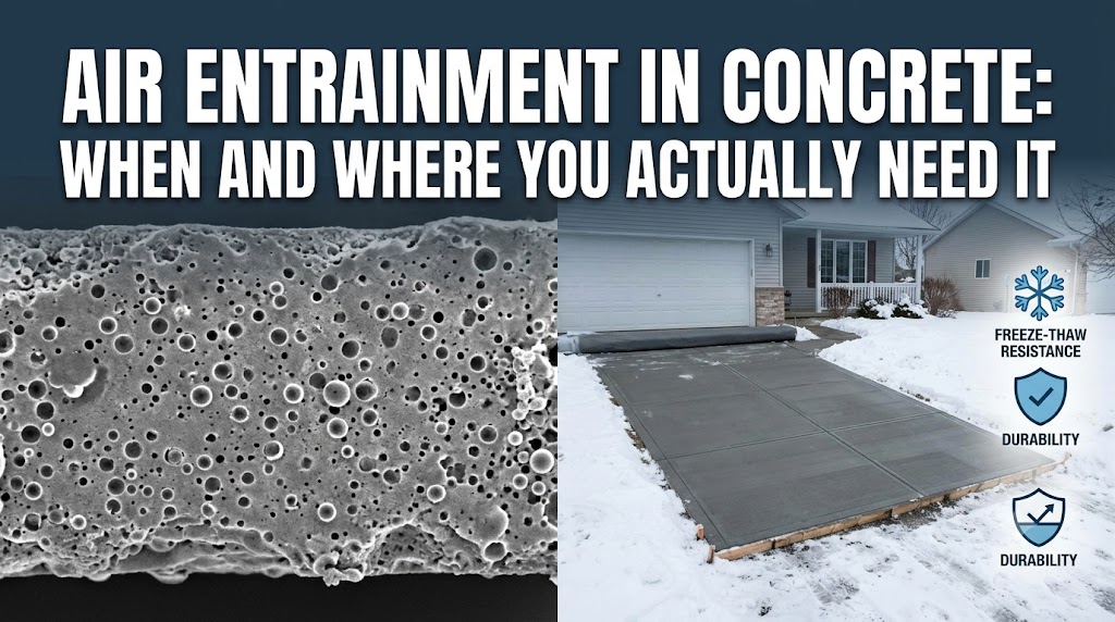
    Air entrainment is mandatory for any concrete that will experience freeze-thaw cycling. Without it, water in the concrete expands when it freezes, generating internal hydraulic pressure that exceeds the tensile strength of the paste and causes progressive surface scaling and spalling. A single winter season is enough to begin visible damage on non-air-entrained flatwork in a climate that cycles between freezing and thawing — which covers most of the northern US, Canada, the UK, northern Europe, and elevated regions of Australia.

    How air entrainment works and what the target air content should be

    Air-entraining admixtures — typically vinsol resin, tall-oil derivatives, or synthetic surfactants — reduce the surface tension of water during mixing, causing billions of microscopic air bubbles (typically 10–300 µm diameter) to form and stabilise within the cement paste. These bubbles are not the same as entrapped air (the large, irregular voids from poor consolidation). Entrained air bubbles are small, uniformly distributed, and deliberately engineered.

    When water in the concrete freezes and expands (water expands roughly 9% by volume on freezing), the entrained air voids act as pressure relief chambers. The expanding ice has somewhere to go. Without those voids, the hydraulic pressure builds until the paste cracks. The mechanism requires the bubbles to be close enough together — the spacing factor between adjacent air voids should be no more than 0.2 mm (0.008 inches) per ACI 318 and ACI 201.2R. This is a function of the total air content and bubble size distribution, not just air percentage alone.

    Use the concrete air entrainment calculator to determine required admixture dosage based on your aggregate size, target air content, and concrete volume. Dosage is sensitive to mix design and ambient temperature — the calculator adjusts for these variables.

    Target total air content by aggregate size, per ACI 318 Table 19.3.3.1:

    Nominal max aggregate sizeMild exposureModerate exposureSevere exposure
    9.5 mm (3/8 in)4.5%6.0%7.5%
    12.5 mm (1/2 in)4.0%5.5%7.0%
    19 mm (3/4 in)3.5%5.0%6.0%
    25 mm (1 in)3.0%4.5%6.0%
    37.5 mm (1.5 in)2.5%4.5%5.5%

    Severe exposure: concrete exposed to freeze-thaw cycles in a moist condition and to deicing salts. Moderate: freeze-thaw cycles without deicing chemicals. Mild: occasional freezing with low saturation. In the UK and Ireland, BS 8500-1 uses equivalent exposure classes (XF1–XF4), with XF4 (road and bridge decks with de-icing salts) requiring 4–7% total air.

    Where air entrainment is actually required — and where it is not

    Required: Any outdoor flatwork in a freeze-thaw climate — driveways, footpaths, patios, parking areas, pool decks, exposed slabs. Any structural element in a freeze-thaw climate that is in a moist or saturated state: retaining walls, foundations at or above grade, bridge decks, pavements. Concrete exposed to deicing salts needs both air entrainment and a low water-cement ratio (0.40 or below per ACI 318 for severe exposure).

    Not required: Interior slabs (garage floors with no external freeze exposure, warehouse floors, basement slabs). Concrete in permanently dry conditions. Concrete in warm climates where air temperature never drops below 0°C / 32°F with the concrete in a saturated state. Mass concrete where thermal mass prevents freeze-thaw cycling.

    Air entrainment is also used — separately from freeze-thaw protection — to improve workability in low-slump mixes. Each 1% of entrained air reduces water demand by approximately 3–5 litres per m³ (0.5–0.9 gal/yd³), which can partially offset the water-cement ratio without reducing workability. This application is less common but relevant in stiff paving mixes.

    Common mistakes

    Specifying air entrainment in interior slabs. Air-entrained concrete used for interior floor slabs that will receive a hard-trowel finish is a significant mistake. The entrained air voids open at the surface during troweling if finishing happens too early or too aggressively, leaving a pitted, weak surface layer. Interior concrete on grade does not experience freeze-thaw cycling — the freeze-thaw protection is irrelevant, and the surface quality penalty is real. Specify non-air-entrained concrete for interior slabs, regardless of what the ready-mix plant offers as a default.

    Not testing air content on site before placement. Air content in the delivered concrete can differ from the batch plant target due to temperature changes in transit, variation in admixture dosage, or aggregate moisture. The only way to know what you are placing is to test it. ASTM C231 (pressure meter method) and ASTM C173 (volumetric method, for lightweight or slag aggregates) both take under five minutes. Accepting a truckload without testing the air content is standard practice in residential work — and the reason many residential driveways fail within three winters.

    Finishing air-entrained concrete too early. Troweling before bleed water has fully evaporated seals the surface and traps moisture below, which later forms a weak delamination layer. The correct trigger for finishing is when the bleed water sheen disappears and the surface can support the finisher’s weight without significant indentation — typically 1–3 hours depending on temperature and relative humidity. Premature finishing is responsible for the majority of surface scaling complaints on air-entrained flatwork.

    Assuming higher air content is always better. Air content above the ACI maximum for a given aggregate size begins to reduce compressive strength significantly — roughly 5% strength reduction per 1% increase in total air content. An over-entrained mix at 9–10% total air on a 19 mm aggregate may meet the durability goal but drop compressive strength by 15–20% relative to the designed mix. If you need both freeze-thaw durability and high strength (for example, a driveway subject to deicing salts), the solution is the correct air content range plus a low water-cement ratio, not excess air.

    Related calculators you might need

    Air entrainment works best when the rest of the mix design is also dialled in. The water-cement ratio calculator is particularly important here: ACI 318 requires a maximum w/c of 0.40 for concrete exposed to deicing chemicals and freeze-thaw in a moist condition. If you are adding an air-entraining admixture alongside other chemical admixtures (a water reducer, for instance), the concrete admixture dosage calculator helps you calculate combined dosages and check compatibility. For driveways and patios specifically, the concrete driveway calculator and concrete patio calculator give you the volume to order — take that figure to the batch plant along with your specified air content range.

    Frequently asked questions

    Does all concrete in cold climates need air entrainment?

    Only concrete that will be in a moist or saturated condition when freezing temperatures arrive. A concrete foundation below a heated building, for instance, may not be subject to freeze-thaw cycling even in a cold climate. The critical combination is: concrete that is wet (above roughly 80% internal relative humidity) AND subject to temperatures cycling below 0°C / 32°F. Outdoor flatwork in any northern US state, Canadian province, or most of northern and central Europe meets both conditions by default. Specify air entrainment for all exposed outdoor concrete in these regions without exception.

    What happens if air content is too low or too high?

    Too low (below the minimum target range): freeze-thaw damage begins within 1–3 seasons in cold climates. Surface scaling appears first — a characteristic flaking of the top 1–3 mm of paste — followed by progressive aggregate exposure and structural deterioration. Too high (above the maximum target range): compressive strength drops and surface finishability suffers. At 2–3% above the maximum ACI target, strength reduction is meaningful (10–15% on some mix designs). The target range is a range for a reason — aim for the midpoint at the batch plant.

    Can I add air-entraining admixture to a bagged concrete mix?

    Yes, but it requires careful dosing. Standard bagged concrete mixes (Quikrete 5000, Sakrete, etc.) do not contain air-entraining admixture. You can add a liquid air-entraining admixture to the mix water at the manufacturer’s recommended dosage per bag. The challenge is that hand-mixing produces inconsistent air distribution — a drum mixer gives better results. You will not be able to verify air content without a pressure meter, so testing is impractical for small site mixes. For a driveway, walkway, or patio in a freeze-thaw climate, ready-mix concrete with specified and tested air content is a considerably more reliable option than trying to air-entrain bagged concrete on site.

    How do I know if my ready-mix supplier is delivering the right air content?

    Ask for the batch ticket with every load and check that the air-entraining admixture dosage is consistent with what you specified. More importantly, perform an on-site air content test using a Type B pressure meter (ASTM C231) on the first truck of every pour. Target your specified range — typically 5.5–7.5% for a residential driveway in a severe exposure climate. If the test comes in below 4.5% or above 8.5% on standard aggregate, reject or hold the load and call the plant to adjust before pouring.

    Does air entrainment affect concrete colour or appearance?

    Air-entrained concrete is slightly lighter in colour when fresh compared to non-air-entrained concrete of the same mix design — the additional voids reduce the density of the paste. After curing and sealing, the colour difference is minimal for most standard grey or pigmented mixes. The more relevant appearance issue is surface texture: correctly finished air-entrained concrete looks the same as non-air-entrained concrete. Incorrectly finished concrete (troweled too early or too aggressively) will show a pitted surface from air voids opening at the paste surface.

    Can air entrainment fix concrete that was not air-entrained at placement?

    No. Air entrainment is a mix design decision made at the batch plant. Once concrete is placed and hardened, there is no way to add or improve freeze-thaw durability through surface treatments alone. Penetrating sealers reduce surface water absorption and extend the service life of non-air-entrained flatwork in mild exposure conditions, but they are not a substitute for entrained air in a severe freeze-thaw environment. If a driveway or patio was placed without air entrainment in a climate where it was required, the realistic outcome is resurfacing or replacement within 5–10 years.

  • Concrete Pigments: How to Calculate Color Dosage Accurately

    Concrete Pigments: How to Calculate Color Dosage Accurately

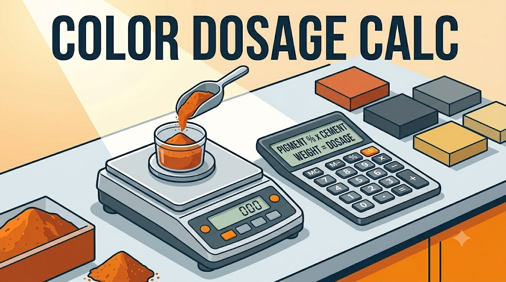
    Concrete pigment dosage is expressed as a percentage of cement weight, not concrete volume. Get that relationship wrong and you will either produce a washed-out result at under 2% or waste expensive pigment — and risk strength reduction — above 10%. The standard working range is 2% to 8% of cement weight, with most saturated colours landing at 5–6%.

    How to calculate concrete pigment dosage

    The formula is straightforward:

    Pigment weight = Cement weight × Dosage percentage

    Example: A 1 m³ batch using a 1:2:3 mix by weight contains approximately 350 kg of cement. At a 5% dosage for a medium red-oxide colour: 350 × 0.05 = 17.5 kg of pigment per m³. At a typical retail price of $3.50–$6.00 per kg for iron oxide pigment, that adds $61–$105 per m³ to the concrete cost.

    Use the concrete pigment and color calculator to enter your cement content, target dosage, and number of batches — it outputs total pigment weight and flags you if your dosage falls outside the standard performance range.

    For bagged concrete, work backwards from the bag label. An 80 lb (36.3 kg) bag of standard concrete mix typically contains about 10 lb (4.5 kg) of cement. A 5% dosage means 0.5 lb (0.23 kg) of pigment per bag — across a 10-bag pour, that is 5 lb (2.3 kg) of pigment. Manufacturers sometimes publish this as a ratio: “1 lb pigment per bag” which implies roughly 10% — toward the upper limit and not representative of all colours.

    Why dosage percentage matters: the chemistry behind colour saturation

    Concrete pigments are almost universally inorganic iron oxide compounds — red (Fe₂O₃), yellow (FeOOH), black (Fe₃O₄), and brown (mixed oxides). Chromium oxide gives green; cobalt aluminate gives blue. These are not dyes. They do not dissolve into the cement paste — they coat the cement particles and fill the interstitial spaces between aggregate. Colour intensity is a function of pigment particle concentration relative to the total binding surface available.

    Below 2% of cement weight, pigment concentration is too low to produce a consistent tone — the grey of the cement matrix dominates and the result looks diluted regardless of the pigment colour. Between 2% and 6%, colour intensity increases roughly proportionally with dosage. Above 6%, returns diminish significantly and the additional pigment particles begin to interfere with cement hydration by coating cement grains before they can fully react. Above 10%, strength loss is measurable — ASTM C979 (US) and BS EN 12878 (UK/EU) both set 10% as the maximum permitted dosage for this reason.

    White Portland cement produces substantially more vivid colours than grey cement at the same dosage. A 5% red oxide dose on white cement will be a saturated terracotta; on grey cement, it will be a muted brick-brown. For high-saturation colour work — stamped concrete, exposed aggregate, decorative flatwork — specifying white cement base is worth the 20–30% cement cost premium.

    Dosage reference by colour type and application

    Colour / Pigment typeTypical dosage rangeNotes
    Red / iron oxide red3%–6% of cement wt.Most common pigment; performs well on both grey and white cement
    Yellow / iron oxide yellow3%–7% of cement wt.Heat-sensitive above 300°C — avoid in fire-exposed applications
    Black / iron oxide black1%–3% of cement wt.Highly efficient — low dosage achieves deep tone; easy to over-dose
    Brown / mixed iron oxide3%–6% of cement wt.Blended product; shade varies significantly by supplier
    Green / chromium oxide3%–6% of cement wt.More expensive than iron oxides; better UV stability
    Blue / cobalt aluminate2%–5% of cement wt.Most expensive option; typically requires white cement base
    White / titanium dioxide5%–10% of cement wt.Used to lighten concrete on white cement base; large volume required

    Common mistakes

    Measuring pigment by volume instead of weight. Pigment density varies widely by type — titanium dioxide is roughly 4.2 g/cm³; synthetic iron oxide is around 4.8–5.2 g/cm³. A cup of black iron oxide and a cup of titanium dioxide weigh different amounts and require different dosages. Always weigh pigment on a scale calibrated to ±10 g or better. Using scoops or volume estimates across a multi-batch pour will produce visible colour variation between pours.

    Inconsistent cement content between batches. Colour consistency depends on a fixed ratio of pigment to cement. If one batch uses 320 kg of cement and the next uses 370 kg, and both get the same weight of pigment, the second batch will be noticeably lighter. Use the concrete batch calculator to lock your mix proportions and scale them identically for every batch in the same pour.

    Adding pigment directly to dry cement before water. Dry blending pigment into cement before adding aggregate and water is the correct method for hand-mixing. Some contractors add pigment to the water instead — this leads to clumping in some pigment types and uneven distribution in the mix. The correct sequence is: aggregate, cement, pigment (dry-blended), then water. For ready-mix, the batch plant adds pigment with the cement and aggregate in the drum before water.

    Not accounting for sealer or coating effects on the final colour. A penetrating sealer darkens concrete by 10–20%; a film-forming sealer can shift apparent colour significantly depending on its tint. Any colour sample or test slab assessment must be done with the sealer already applied. Assessing colour on bare concrete and then applying a sealer without re-checking produces an unpredictable final result.

    Related calculators you might need

    Once you know your pigment dosage, the next step is making sure your cement quantity is calculated accurately — because the dosage is a direct function of it. Use the cement quantity calculator to get exact cement weight per batch or per cubic metre. If you are mixing on site in multiple batches that all need to match, the concrete batch calculator keeps your proportions consistent pour to pour. For stamped concrete projects where colour is a primary decision, the stamped concrete calculator estimates volume and material cost for the full job.

    Frequently asked questions

    How much pigment do I add per bag of concrete?

    An 80 lb / 36 kg bag of premixed concrete contains roughly 9–11 lb / 4–5 kg of cement. At a 5% dosage, you need approximately 0.45–0.55 lb / 200–250 g of pigment per bag. For a 10-bag pour, that is about 5 lb / 2.3 kg total. Pigment manufacturers often publish simpler ratios — check the product data sheet, as dosages vary by pigment type and the shade you want. Use the concrete pigment and color calculator to generate exact weights for your specific batch.

    Will adding pigment weaken my concrete?

    At dosages up to 6% of cement weight, iron oxide pigments have no measurable effect on 28-day compressive strength in standard mixes. Between 6% and 10%, minor strength reduction is possible but typically within 5–8% — acceptable for most applications. Above 10%, strength loss becomes significant and is explicitly limited by ASTM C979 and BS EN 12878. Black iron oxide at high dosage has been shown to slightly retard setting time. If strength is critical, specify the mix design with the pigment included and test samples at 28 days.

    Does concrete colour fade over time?

    Iron oxide pigments are among the most UV-stable colourants available — far more stable than organic dyes. Colour fade over 10–20 years is minimal when the concrete is sealed and maintained. What changes colour more noticeably is carbonation (surface greyening from CO₂ reaction with calcium hydroxide), efflorescence (white salt deposits), and surface wear. Resealing every 3–5 years maintains both the colour and the surface protection. Black is the most fade-resistant colour; yellow iron oxide is the least stable at elevated temperatures.

    Can I mix two pigment colours together?

    Yes. Iron oxide pigments are compatible with each other and can be blended dry before adding to the mix. Stick to pigments from the same supplier to avoid unexpected reactions — though iron oxides from different manufacturers are generally inert to each other. Test your blend on a sample slab before committing to a full pour. Colour shifts slightly when wet versus dry and again after curing — the only reliable reference is a cured, sealed sample in the same mix design and cement type you will use on the job.

    What is the difference between liquid pigment and powder pigment for concrete?

    Liquid pigments are pre-dispersed in water and are easier to mix uniformly — they are standard in ready-mix batch plants. Powder pigments are more concentrated by weight and more cost-effective for site mixing. Both produce equivalent results when dosed correctly by weight (liquid pigment dosage is quoted per litre of concentrate, which corresponds to a dry pigment equivalent on the product data sheet). For hand-mixing, powder is more practical. For ready-mix truck delivery, specify the dosage to the batch plant and confirm whether they use liquid or powder so you can provide the equivalent dosage.

  • Fiber Reinforcement vs Rebar: A Real-World Comparison

    Fiber Reinforcement vs Rebar: A Real-World Comparison

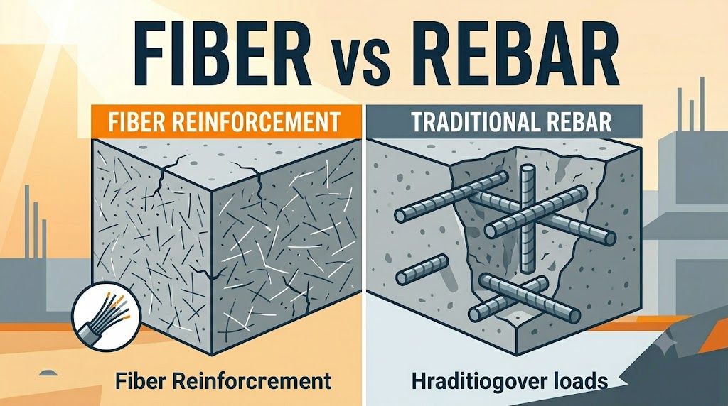
    Fiber reinforcement does not replace rebar for structural applications. That is the most important thing to understand before comparing the two. Fibers control shrinkage cracking and improve toughness; rebar carries tensile load. Choosing between them — or combining them — depends entirely on what the concrete is being asked to do.

    How fiber reinforcement and rebar actually work

    Concrete is strong in compression and weak in tension. Rebar solves the tension problem by embedding steel bars that carry tensile forces the concrete cannot handle alone. This is structural reinforcement: it prevents failure under load and keeps a cracked section from separating. Without it, a loaded slab or beam can crack through and collapse.

    Fiber reinforcement works differently. Synthetic fibers — typically polypropylene at 12–19 mm for micro-fibers, or nylon and polyester for macro-fibers — are distributed randomly throughout the mix. They do not form a continuous load path the way a rebar mat does. What they do is bridge micro-cracks as they form, limiting crack width and slowing propagation. Steel fibers (typically 30–60 mm, hooked-end) can carry meaningful post-crack load in industrial flooring, but they still cannot replicate the directional tensile capacity of a placed rebar layout in structural members.

    The concrete fiber reinforcement calculator lets you calculate dosage by volume and project size for both synthetic and steel fiber types.

    Side-by-side comparison: cost, labour, lifespan, and use cases

    This table covers the real decision variables — not theoretical ones.

    FactorSynthetic Micro-FiberSteel / Macro-FiberRebar (mild steel)
    Material cost (per m³ / yd³)$3–$8 / $2.50–$6.50$18–$45 / $15–$38$20–$80+ depending on layout
    Labour impactMixed in with batch — zero extra placement labourSame as synthetic — no placement workRequires cutting, bending, tying, and placement; adds 1–4 hrs per 10 m² / 110 ft²
    Crack controlControls plastic and early drying shrinkage cracksControls shrinkage and improves post-crack toughnessControls structural cracks under load; minimal effect on early shrinkage
    Structural capacityNonePartial — only in certain slab-on-grade designs with engineering approvalFull — designed tensile capacity per ACI 318 / AS 3600 / BS EN 1992
    Typical lifespanSame as the concrete — 30–50+ yearsSame as the concrete if corrosion-resistant type used50–100 years with adequate cover; shorter if corrosion occurs
    Best use casesFootpaths, driveways, patios, pool decks, residential slabsIndustrial floors, warehouse slabs, precast elementsFootings, beams, columns, retaining walls, any structural element

    When fiber alone is sufficient — and when it is not

    Micro-synthetic fibers are sufficient for any non-structural flatwork where the primary risk is plastic shrinkage cracking: residential driveways, sidewalks, patios, shed pads, and pool decks. At a typical dosage of 0.6–0.9 kg/m³ (1.0–1.5 lb/yd³), they distribute into millions of filaments per cubic metre and intercept micro-cracks before they become visible. The concrete still cracks — all concrete cracks — but the cracks stay narrow and do not open up.

    Where fiber reinforcement is not sufficient:

    Any element that carries load in bending — beams, suspended slabs, lintels — needs rebar. The tensile stress at the bottom of a loaded beam cannot be resisted by randomly distributed short fibers. Any retaining wall resisting lateral earth pressure needs rebar, typically at both faces. Any footing transferring column or wall loads to soil needs rebar. Fibers in these applications are a secondary addition at best, not a substitute.

    Steel fibers in industrial slab-on-grade applications are a different conversation. Dosages of 25–40 kg/m³ (42–67 lb/yd³) can replace conventional rebar mats in ground-supported floors where the primary loading is distributed (forklifts, racking loads) and joint-free slab construction is the goal. This requires a structural engineer, a fibre supplier’s design tool, and compliance with TR34 (UK/international) or ACI 360 (US).

    Common mistakes

    Treating micro-fibers as a one-for-one rebar substitute in structural work. This is the most dangerous misunderstanding in the comparison. A contractor who swaps out a rebar mat for a fiber dose in a footing or retaining wall has not simplified the job — they have created a structural deficiency. Micro-fibers carry zero tensile load in a cracked section under sustained stress. The correct approach: use fibers for shrinkage control and rebar for structural performance, often together.

    Using rebar to solve a plastic shrinkage cracking problem. If a slab cracks within the first 24 hours — before the concrete has hardened — rebar provides no benefit. Plastic shrinkage cracking is caused by the surface drying faster than water bleeds up from below. The fix is fiber reinforcement (prevents crack initiation), windbreaks, evaporation retarder, and curing covers — not additional steel.

    Inadequate rebar cover. The standard minimum cover for rebar in a slab-on-grade is 38 mm / 1.5 inches from the bottom. Contractors who place chairs incorrectly — or none at all — end up with rebar sitting at mid-depth or lower, where it contributes almost nothing to flexural capacity. Rebar at mid-slab resists neither top-fibre tension nor bottom-fibre tension effectively.

    Assuming all fibers are equivalent. A 12 mm polypropylene micro-fiber added at 0.6 kg/m³ is a crack-control additive. A 50 mm hooked-end steel fiber at 35 kg/m³ is a structural material. Using the former in an industrial floor application and expecting structural-grade crack resistance is a dosage and product mismatch. Check the fiber type, length, aspect ratio, and the supplier’s dosage curves.

    Related calculators you might need

    If you are designing the reinforcement layout for a slab, the rebar spacing calculator converts your bar size and spacing into total weight and linear metres — useful when comparing the steel cost against a fiber dosage. For the concrete itself, the concrete mix ratio calculator helps you confirm that the base mix design is compatible with fiber addition (water-cement ratio and workability both affect fiber distribution). If the project involves a structural slab and you need to verify load capacity, the concrete load capacity calculator gives you a working baseline before involving a structural engineer.

    Frequently asked questions

    Can I add fiber to a mix that already has rebar?

    Yes — combining both is standard practice in industrial slabs, driveways, and concrete structures in aggressive environments. Synthetic micro-fibers control early shrinkage cracking independently of the rebar layout. Steel fibers in structural-grade dosages can sometimes allow rebar reduction, but only with engineering sign-off. For most residential and commercial flatwork, adding 0.6–0.9 kg/m³ of polypropylene fiber to a rebar-reinforced slab is straightforward and has no negative effect on the rebar.

    Is fiber reinforcement cheaper than rebar?

    For the material alone, micro-synthetic fibers typically add $3–$8 per m³ ($2.50–$6.50 per yd³), which is cheaper than most rebar layouts. The real cost difference is labour: rebar requires cutting, tying, and placing, which adds meaningful time on site. For a 100 m² / 1,075 ft² driveway, rebar placement can add 6–8 hours of skilled labour. Fiber is added at the batch plant and requires nothing on site. However, if structural reinforcement is required, rebar is not optional — no labour saving justifies the omission.

    What does fiber reinforcement actually do to concrete strength?

    Micro-synthetic fibers at standard dosages (0.6–0.9 kg/m³) have no meaningful effect on compressive strength — typically less than 1–2 MPa difference. They improve toughness (energy absorption after cracking) and reduce plastic shrinkage crack width by 80–90% in controlled tests. Steel fibers at high dosages (30–40 kg/m³) increase post-crack flexural strength and toughness substantially, which is why they are used in industrial floor design. Neither fiber type increases the 28-day compressive strength the way an improved mix design or lower water-cement ratio would.

    Does fiber reinforcement stop concrete from cracking entirely?

    No. Every concrete element will crack at some point — thermal movement, drying shrinkage, and load-induced stress all exceed concrete’s tensile strength under normal service conditions. What fibers do is limit crack width and spacing. A slab with synthetic fibers at adequate dosage will still crack, but the cracks will be narrower (typically under 0.2 mm at early age) and more numerous rather than fewer wide cracks. That is the desired outcome: distributed fine cracks are structurally and aesthetically less damaging than isolated wide ones.

    How do I calculate the right fiber dose for my project?

    Standard residential dosage for polypropylene micro-fiber is 0.6 kg/m³ (1.0 lb/yd³) for general flatwork, and up to 0.9 kg/m³ (1.5 lb/yd³) for slabs with higher shrinkage risk (large surface area, hot weather, low humidity). Use the concrete fiber reinforcement calculator to convert your slab volume into total fiber weight by dosage rate. For steel fiber in industrial applications, use the supplier’s design guide — dosage ranges from 20 to 40 kg/m³ depending on the design method and loading scenario.

    Can I use fiber reinforcement in footings?

    Micro-synthetic fibers in footings control plastic shrinkage cracking during cure, which is useful in hot conditions. They do not, however, provide the tensile reinforcement that footings require. A strip footing, pad footing, or pile cap must have rebar sized and placed to an engineer’s specification. Adding fibers to a footing mix is acceptable as a secondary measure but does not reduce or eliminate the rebar requirement under any major building code.

  • Concrete Footing Depth: Frost Line, Soil Type & Building Codes

    Concrete Footing Depth: Frost Line, Soil Type & Building Codes

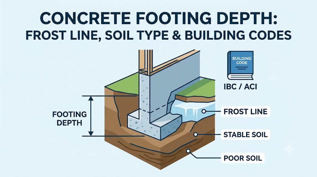
    Footings must bear below the frost depth for your location or they will heave. The frost depth in Minneapolis, Minnesota is 42 inches (1,067 mm); in Atlanta, Georgia it is 6 inches (150 mm); in Miami it is effectively zero. Use the Frost Depth / Footing Depth Calculator to get the minimum footing depth for your ZIP code or postal region, then confirm against your local authority’s amendment to the model code.

    How to Determine Required Footing Depth

    Footing depth is governed by two separate requirements that must both be met: frost penetration depth (to prevent frost heave) and bearing depth (to reach soil with adequate bearing capacity). The greater of the two values governs. In most northern US and Canadian locations, frost depth governs. In warm climates and on rock substrates, bearing capacity typically governs.

    Frost depth across North America

    Frost depth is measured as the depth to which soil freezes in an average winter. It is expressed as a function of cumulative freezing degree-days (the sum of daily mean temperatures below 32°F / 0°C over the winter season). The US Army Corps of Engineers publishes frost depth maps based on this methodology, and the International Residential Code (IRC) Table R301.2(1) requires frost depth data to be listed in each local amendment.

    City / RegionFrost DepthCode Reference
    Anchorage, AK72 in / 1,829 mmLocal amendment
    Minneapolis–St. Paul, MN42 in / 1,067 mmMN State Building Code
    Chicago, IL42 in / 1,067 mmIL Plumbing Code R403.1.4.1
    Denver, CO36 in / 914 mmLocal amendment
    New York City, NY36 in / 914 mmNYC BC §1809.5
    Seattle, WA12 in / 305 mmWSBC R403.1.4.1
    Atlanta, GA6 in / 150 mmGA State Minimum Standard Code
    Dallas, TX6 in / 150 mmLocal amendment
    Miami, FL0 in / 0 mmFrost-free; bearing governs
    Toronto, ON (Canada)48 in / 1,219 mmOBC Division B A-9.12.2.2
    Calgary, AB (Canada)48 in / 1,219 mmAB Building Code Div. B
    Vancouver, BC (Canada)18 in / 457 mmBC Building Code

    Frost depth in the UK, Europe, and Australia

    The UK does not experience the same frost penetration severity as northern North America. NHBC Standards Chapter 4.2 requires foundations to extend at least 450 mm (18 inches) below finished ground level in most of England, Scotland, and Wales to avoid ground movement from frost and shrinkable clays. The 450 mm figure is a practical minimum, not a frost depth; clay shrinkage from seasonal moisture change is a greater concern in southern England than frost.

    In Scandinavia, frost depths are substantial: Oslo averages 1.0–1.2 m (39–47 inches) and Stockholm averages 0.8–1.1 m (31–43 inches). The Nordic building codes (NS-EN 1997-1 in Norway, BFS 2019:1 in Sweden) require foundations to extend below the local design frost depth plus a buffer. Central Europe (Germany, Austria, Switzerland) uses frost penetration depths of 0.6–0.8 m (24–31 inches) for most zones. Australia has negligible frost depth in the populated coastal zones; AS 2870 classifies sites by soil reactivity and drainage conditions, not frost.

    Soil Type and Bearing Capacity Requirements

    Bearing capacity is the second determinant of footing depth. Even in frost-free locations, footings must reach soil that can support the load without settlement. The allowable bearing pressure of common soils ranges from 1,500 psf (71.8 kPa) for soft clay to 8,000 psf (383 kPa) for gravel or hard rock. IBC Table 1806.2 and IRC Table R401.4.1 provide presumptive bearing values that can be used without a geotechnical investigation for ordinary structures.

    Soil ClassificationPresumptive Bearing (IBC)Typical Footing DepthNotes
    Bedrock12,000 psf / 574 kPaAt surface if exposedShallow frost not relevant
    Gravel, well-graded3,000 psf / 144 kPa12–18 in / 300–450 mmFrost depth governs in northern zones
    Sandy gravel2,500 psf / 120 kPa18–24 in / 450–600 mm 
    Sand, well-graded2,000 psf / 96 kPa18–36 in / 450–900 mm 
    Silt (ML, MH)1,500 psf / 72 kPa24–48 in / 600–1,220 mmFrost-susceptible; avoid near frost line
    Clay (CL)1,500 psf / 72 kPa24–48 in / 600–1,220 mmExpansive potential; check Atterberg limits
    Soft clay or organic soilNot listed; test requiredEngineer requiredDo not use presumptive values

    Expansive clays — soils with plasticity index above 20 — present an additional constraint beyond bearing capacity. In the US Southwest (Texas, Oklahoma, California), expansive clay movement can be 3 to 8 inches (75–200 mm) seasonally, which requires either a deep drilled pier system, a post-tensioned slab designed for the differential movement, or soil treatment. Frost heave and clay expansion can act simultaneously in northern Texas and Oklahoma, compounding the design challenge.

    Building Code Minimum Footing Depths by Application

    The IRC Section R403.1.4 establishes that exterior footings must bear below the frost line and at least 12 inches (305 mm) below undisturbed soil surface — whichever is deeper. Interior footings in heated buildings are exempt from the frost requirement under IRC R403.1.4.1 Exception 2, since the building heat prevents soil freezing. However, most code officials require documentation that the building will remain continuously heated; unheated garages and barns do not qualify for this exemption.

    Deck footings are the most common frost violation in residential construction. Many homeowners install deck post footings using pre-mix concrete poured to only 12 inches (305 mm) depth, which is adequate in Atlanta but will heave annually in Chicago. A 48-inch (1,219 mm) deep tube footing with a 12-inch (305 mm) diameter bell is standard for deck posts in Frost Zone D (Chicago, Minneapolis). The Concrete Tube / Sonotube Calculator calculates the volume for cylindrical tube footings at any depth and diameter.

    Common Mistakes in Footing Depth

    Mistake 1 — Using the national minimum without checking the local amendment. IRC R403.1.4 sets a process, not a number. The actual frost depth is set by each local jurisdiction, and many jurisdictions have adopted amendments that are more restrictive than the base code. The city of Minneapolis requires footings at 42 inches (1,067 mm) minimum; some counties in Minnesota require 48 inches (1,219 mm). Always confirm with the local building department, not a national table.

    Mistake 2 — Assuming heated buildings are always exempt from frost requirements. The interior heated-building exemption applies to interior footings only — footings inside the building thermal envelope. Exterior footings — including those under a heated building’s perimeter walls — must still bear below frost depth. Contractors sometimes misread this exemption and shorten perimeter footings, leading to differential settlement between interior and perimeter support points.

    Mistake 3 — Ignoring frost-susceptible soil classification. The US Army Corps of Engineers Frost Design Soil Classification (CRREL Report 80-28) identifies silt and fine sand as highly frost-susceptible (FS3 and FS4 categories), meaning they will heave significantly even at shallow frost depths if water is present. A footing on frost-susceptible silt in Denver (36-inch frost depth) must penetrate to 36 inches (914 mm) minimum, not to the first firm layer. On non-frost-susceptible soils like gravel, frost heave is negligible and shallow footings can be acceptable with drainage provisions.

    Mistake 4 — Sizing footing width only for bearing, not for column loads. Footing depth addresses frost and bearing depth. Footing width addresses bearing area. Specifying a 12-inch (305 mm) wide footing at 42 inches (1,067 mm) deep for a 30,000 lb (13,608 kg) column load on 1,500 psf (72 kPa) clay produces a bearing stress of 2,500 psf (120 kPa) — well above the allowable. The correct footing width for that scenario is 30,000 ÷ 1,500 = 20 square feet, requiring at minimum a 4.5 ft × 4.5 ft (1.37 m × 1.37 m) pad. The Concrete Footing Calculator calculates both dimensions and concrete volume simultaneously.

    Related Calculators You Might Need

    After confirming footing depth, the volume calculation is the immediate next step. The Concrete Footing Calculator handles continuous strip footings, isolated pad footings, and combined configurations. For deck and post applications, the Post Hole Concrete Calculator handles cylindrical and tapered holes with or without tube forms.

    If the project involves a full perimeter foundation, the Concrete Foundation Wall Calculator estimates wall volume and forming area. For projects in the northern US or Canada where frost depth drives the design, the Frost Depth / Footing Depth Calculator provides location-specific depth data and integrates with the footing volume calculation.

    Frequently Asked Questions

    How deep should concrete footings be?

    It depends on your location’s frost depth and soil bearing capacity. In frost-free zones (Miami, coastal California, most of Australia), 12 inches (305 mm) is generally adequate for residential structures on competent soil. In northern US climates, depths of 36 to 48 inches (914–1,219 mm) are standard. The Frost Depth / Footing Depth Calculator provides the correct minimum for your specific location.

    What happens if footings are not deep enough?

    Footings above the frost line will heave upward as soil freezes and expands, then settle back as it thaws. This seasonal movement — often 1 to 3 inches (25–75 mm) — cracks masonry walls, breaks plumbing connections, racks door frames, and damages finishes. Structural repair after frost heave damage is expensive, typically requiring either underpinning the existing footing or demolishing and rebuilding the affected section.

    Can I use a shallow footing in a heated building?

    Interior footings inside the building’s thermal envelope are exempt from frost depth requirements under IRC R403.1.4.1 Exception 2, because building heat prevents soil from freezing. However, the footing must still extend to bearing soil. This exemption does not apply to exterior perimeter footings, unheated garages, pole barns, or structures that may be unoccupied for extended winter periods.

    What is the frost line in my area?

    The frost line (also called frost depth or freezing depth) is the maximum depth at which soil temperatures drop below freezing during a standard winter. It ranges from 0 inches in Miami to over 72 inches (1,829 mm) in interior Alaska. In the contiguous US, the IRC Table R301.2(1) directs you to the local jurisdiction’s adopted value. Canadian provinces publish frost depth maps through the National Building Code Supplementary Technical Requirements. In the UK, 450 mm (18 inches) is the standard minimum footing depth from NHBC, covering both frost and clay shrinkage.

    Does soil type affect how deep footings need to be?

    Yes, in two ways. First, soft or organic soils may not provide adequate bearing capacity at the frost depth, requiring deeper excavation to reach competent bearing material. Second, frost-susceptible soils (silts and fine sands classified as FS3 or FS4) can heave significantly even at modest frost depths if water is present. On gravel or coarse sand (non-frost-susceptible, good drainage), the same frost depth causes negligible heave. Soil classification affects both the required depth and the need for drainage provisions.

    How wide should concrete footings be?

    Footing width is determined by dividing the total load by the allowable bearing pressure of the soil. For a 6-inch (150 mm) concrete block wall exerting 3,000 lb/linear ft (43.8 kN/m) on soil with 1,500 psf (72 kPa) allowable bearing, the required footing width is 3,000 ÷ 1,500 = 2 linear feet (610 mm). IRC R403.1 requires a minimum footing width of 12 inches (305 mm) for one-storey construction regardless of the calculation result. The Concrete Footing Calculator walks through both the depth and width determination.

  • Wire Mesh vs Rebar: Load Capacity Compared

    Wire Mesh vs Rebar: Load Capacity Compared

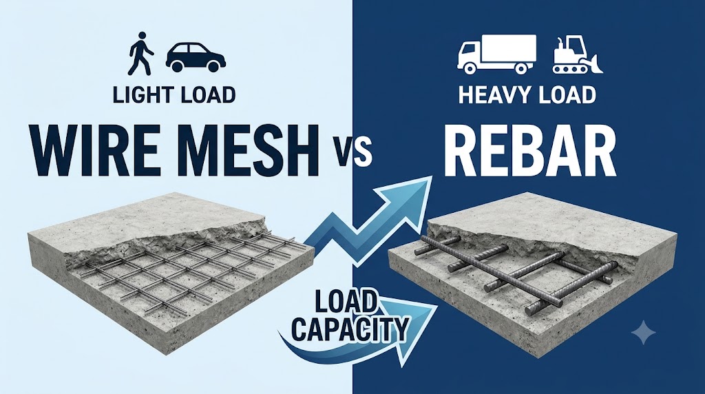
    Wire mesh (welded wire fabric, WWF) controls shrinkage and temperature cracking in lightly-loaded slabs. Rebar carries structural loads and provides the tensile reinforcement that allows concrete to resist bending under wheel loads, point loads, and frost pressure. For a residential patio or sidewalk, 6×6 W1.4/W1.4 mesh is adequate. For a driveway, garage floor, or any slab carrying vehicles, rebar at #3 or #4 at 12–18 inches (305–457 mm) on centre outperforms mesh in every load scenario. Use the Wire Mesh / Welded Wire Fabric Calculator to quantify mesh for light-duty applications, or the Rebar / Reinforcing Steel Calculator for structural slab reinforcement.

    What Wire Mesh and Rebar Actually Do in a Slab

    Unreinforced concrete has high compressive strength but almost no tensile capacity — roughly 8 to 12% of its compressive strength in direct tension. When a slab bends under load, the bottom face goes into tension, and unreinforced concrete cracks at low stress. Both mesh and rebar address this by providing steel, which has a tensile yield strength of 60,000 psi (414 MPa) for Grade 60 rebar and 65,000–80,000 psi (448–552 MPa) for common welded wire fabric, to carry the tension the concrete cannot sustain.

    The difference is in cross-sectional steel area per unit width, which governs how much tensile force the reinforcement can carry. This value, typically expressed in square inches per linear foot (in²/ft) or square millimetres per metre (mm²/m), determines the flexural strength of the reinforced section and is the basis of any load capacity comparison.

    Reinforcement TypeSteel Area (per ft / per m)Yield StrengthTypical Use
    6×6 W1.4/W1.4 WWF0.028 in²/ft (59 mm²/m)65,000 psi / 448 MPaFoot traffic, patio, sidewalk
    6×6 W2.9/W2.9 WWF0.058 in²/ft (123 mm²/m)65,000 psi / 448 MPaLight residential slabs
    4×4 W2.9/W2.9 WWF0.087 in²/ft (184 mm²/m)65,000 psi / 448 MPaModerate residential
    #3 rebar @ 18 in o.c.0.073 in²/ft (155 mm²/m)60,000 psi / 414 MPaResidential driveway, garage
    #3 rebar @ 12 in o.c.0.110 in²/ft (233 mm²/m)60,000 psi / 414 MPaResidential driveway
    #4 rebar @ 18 in o.c.0.133 in²/ft (282 mm²/m)60,000 psi / 414 MPaResidential driveway, light commercial
    #4 rebar @ 12 in o.c.0.200 in²/ft (424 mm²/m)60,000 psi / 414 MPaCommercial parking, garage floor
    #5 rebar @ 12 in o.c.0.310 in²/ft (657 mm²/m)60,000 psi / 414 MPaIndustrial floor, heavy truck access

    The table illustrates the central issue: the most common wire mesh specification — 6×6 W1.4/W1.4 — provides only 0.028 in²/ft (59 mm²/m) of steel area per direction, less than one-quarter of the area provided by #4 rebar at 12 inches (305 mm) on centre. This is not a code-compliant substitution for structural reinforcement.

    Load Capacity: Side-by-Side Comparison

    Load capacity comparison requires fixing slab thickness, concrete strength, and subgrade conditions. The scenario below uses a 5-inch (125 mm) slab on compacted gravel subbase, concrete compressive strength f’c = 4,000 psi (27.6 MPa), and the Portland Cement Association (PCA) design method for slabs on ground. The reference vehicle is a standard passenger car with a maximum single-axle load of 5,000 lb (2,268 kg) and a pickup truck / light SUV at 9,000 lb (4,082 kg) single axle.

    ReinforcementAllow. Single-Axle LoadAllow. Uniform LoadPass/Fail: Pickup Truck
    None (plain concrete)~6,000 lb / 2,722 kg~250 psf / 12.0 kPaMarginal — low fatigue life
    6×6 W1.4/W1.4 WWF~6,500 lb / 2,948 kg~260 psf / 12.4 kPaMarginal — minimal gain over plain
    6×6 W2.9/W2.9 WWF~7,500 lb / 3,402 kg~285 psf / 13.6 kPaBorderline pass
    #3 @ 18 in o.c.~9,500 lb / 4,309 kg~340 psf / 16.3 kPaPass
    #4 @ 18 in o.c.~12,000 lb / 5,443 kg~420 psf / 20.1 kPaPass with margin
    #4 @ 12 in o.c.~16,000 lb / 7,258 kg~550 psf / 26.3 kPaPass — commercial grade

    Note: Load values are approximate, derived from PCA TR043 methodology for a 5-inch / 125 mm slab on k = 50 pci / 13.5 MN/m³ subgrade. Actual capacity depends on slab thickness, concrete quality, curing, and joint placement. These figures assume correctly placed reinforcement at mid-depth or slightly below for bottom tension control.

    The critical insight from this comparison is that common wire mesh adds minimal load capacity over plain concrete in the most-used specification (6×6 W1.4/W1.4). It costs more than plain concrete and provides temperature crack control but does not meaningfully increase the load a slab can sustain. Contractors who substitute light mesh for rebar because “it has steel in it” are providing reinforcement that performs structurally close to no reinforcement at all for vehicle loads.

    When Wire Mesh Is the Right Choice

    Wire mesh is appropriate when the function is crack control rather than load bearing. Temperature and shrinkage reinforcement is required by ACI 318 Section 24.4 at a minimum steel ratio of 0.0018 for Grade 60 steel in slabs not exposed to weather or ground. For a 4-inch (100 mm) slab, this requires 0.0018 × 4 × 12 = 0.086 in²/ft (182 mm²/m) — which is met by 4×4 W2.9/W2.9 mesh or #3 bars at 12 inches (305 mm) on centre. The lighter 6×6 W1.4/W1.4 mesh does not meet the ACI minimum temperature and shrinkage requirement for most slab thicknesses.

    Wire mesh genuinely excels in three scenarios: thin topping slabs (1.5–3 inches / 38–75 mm) where bar placement is impractical; precast concrete elements where precise positioning in the form is achieved before casting; and slabs with closely-spaced control joints (every 4–6 feet / 1.2–1.8 m) where the joints limit crack opening and mesh prevents widening at the joint edges. For any application outside these scenarios — especially slabs exposed to vehicle loads — rebar is the correct choice.

    Cost Comparison: Wire Mesh vs Rebar

    Reinforcement OptionMaterial Cost (per 100 sf)Labour ImpactStructural Rating
    6×6 W1.4/W1.4 WWF$18–28 / $194–301 per 100 m²Fast to place; rolls or sheetsCrack control only
    6×6 W2.9/W2.9 WWF$30–45 / $323–484 per 100 m²Slightly heavier; same methodMinimal structural
    #3 rebar @ 18 in o.c.$38–52 / $409–559 per 100 m²Cut, tie, and support barsStructural: light loads
    #4 rebar @ 12 in o.c.$70–95 / $753–1,023 per 100 m²More bars; more tie timeStructural: vehicle loads
    Fiber reinforcement (alt)$12–20 added to mix costNo placement labourCrack control; limited structural

    Material costs are approximate US market rates as of mid-2025. Regional price variation is significant; rebar prices in particular track steel commodity markets. Labour cost differences between mesh and rebar are relevant: mesh sheets or rolls are placed by one worker in minutes; a rebar grid for a 500 sq ft (46.5 m²) slab may take a crew 2 to 3 hours to cut, position, and tie. For small residential slabs where an owner is paying retail labour rates, this difference can exceed the material cost difference.

    Common Mistakes in Choosing Between Wire Mesh and Rebar

    Mistake 1 — Using 6×6 W1.4/W1.4 mesh for a driveway. This is the most common and most consequential error in residential flatwork. Light mesh provides crack control only. A 4-inch (100 mm) driveway slab reinforced with 6×6 W1.4/W1.4 mesh will crack under the first winter of vehicle loading if the subbase is not perfectly prepared, and may crack regardless. Upgrade to #3 or #4 rebar at 18 inches (457 mm) on centre at minimum — and increase thickness to 5 inches (125 mm).

    Mistake 2 — Placing mesh on the ground instead of at mid-depth. Wire mesh resting on the subgrade provides virtually no structural value, since it is at the neutral axis or below it in the slab cross-section. For bottom tension control, reinforcement must be placed in the lower third of the slab — 1 to 1.5 inches (25–38 mm) from the bottom surface. Mesh must be supported on wire chairs or bar chairs during concrete placement. In practice, workers walking on mesh before the pour often push it back to the subgrade. Rebar on chairs stays in position more reliably.

    Mistake 3 — Assuming heavier mesh equals rebar performance. Even 4×4 W4/W4 mesh — a heavy commercial specification — provides 0.120 in²/ft (254 mm²/m), comparable to #4 rebar at 20 inches (508 mm) on centre. This is adequate for light commercial applications, but the welded connections at wire intersections in WWF are not as ductile as bent rebar hooks and laps, reducing the slab’s ability to redistribute load after initial cracking. For post-crack performance in heavy applications, rebar remains superior.

    Mistake 4 — Not accounting for mesh laps. Wire mesh sheets must lap by at least one full mesh spacing — 6 inches (150 mm) for 6×6 mesh — to achieve continuity. Installers frequently butt sheets edge-to-edge, creating a gap in reinforcement at every sheet joint. A butted mesh seam is structurally identical to no reinforcement at that location, and cracks predictably appear along seam lines. Always lap mesh by at least one mesh opening, wired together at the overlap.

    Related Calculators You Might Need

    Once you have decided on rebar, the Rebar Spacing Calculator helps establish the correct grid based on the required steel area and slab thickness. The Rebar / Reinforcing Steel Calculator then converts your layout into a procurement list with linear footage, bar count, and weight. If you are still considering wire mesh for a light application, the Wire Mesh / Welded Wire Fabric Calculator calculates the number of rolls or sheets needed for your slab area including lap allowances.

    For the slab itself, the Concrete Slab Thickness Selector pairs with the reinforcement decision — the required thickness depends on the same load inputs, and both must be sized together. Fibre reinforcement is a third option worth considering for crack control in flatwork; the Concrete Fiber Reinforcement Calculator calculates dosage rates for polypropylene and steel fibres.

    Frequently Asked Questions

    Is wire mesh or rebar better for a concrete driveway?

    Rebar is better for a driveway. Common wire mesh specifications (6×6 W1.4/W1.4) provide only 0.028 in²/ft (59 mm²/m) of steel — insufficient to resist the bending stress from vehicle axle loads. Use #3 bars at 18 inches (457 mm) on centre as a minimum for a residential driveway, or #4 bars at 18 inches (457 mm) on centre where heavy trucks are expected. Combine with a 5-inch (125 mm) minimum slab thickness. The Rebar / Reinforcing Steel Calculator will quantify the material needed.

    Can I use wire mesh in a garage floor?

    For a residential garage floor carrying passenger vehicles, heavy wire mesh — 4×4 W4/W4 or W4.0/W4.0 — can provide borderline adequate crack control on a well-prepared subbase. However, rebar at #3 or #4 at 16–18 inches (406–457 mm) on centre provides significantly more reliable performance at a modest additional cost, and is the preferred specification for any floor that will see regular vehicle use. Light mesh (6×6 W1.4/W1.4) is not adequate for a garage floor.

    Does wire mesh actually prevent concrete from cracking?

    Wire mesh reduces crack width after cracking occurs but does not prevent cracks from initiating. Concrete will crack due to shrinkage regardless of reinforcement type — the reinforcement limits whether those cracks open into visible or structural defects. For shrinkage crack control, ACI 318 requires a minimum steel ratio of 0.0018, which most wire mesh products meet only at very close spacings. Proper joint spacing, adequate subbase preparation, and correct curing do more to prevent cracking than the choice between light mesh and no mesh.

    What does 6×6 W1.4/W1.4 wire mesh mean?

    The designation 6×6 indicates 6-inch (150 mm) wire spacing in both directions. W1.4 is the wire size designation under ASTM A1064, corresponding to a cross-sectional area of 0.014 square inches per wire (9.0 mm²). The two W1.4 values specify the wire sizes in the longitudinal and transverse directions — both W1.4 means a symmetric grid. This is the lightest commercially available structural mesh and is intended for slabs with foot traffic only.

    How much does rebar cost compared to wire mesh for a 500 sq ft slab?

    For a 500 sq ft (46.5 m²) slab: 6×6 W1.4/W1.4 mesh costs roughly $90–140 in materials (two standard 5 ft × 10 ft / 1.5 m × 3.0 m sheets per 50 sq ft). #3 rebar at 18 inches (457 mm) on centre in both directions requires approximately 670 linear feet (204 m) of bar, costing $160–220 at current prices. The rebar option costs roughly $70–100 more in materials but provides a structurally meaningful increase in load capacity for vehicle-bearing slabs.

  • Rebar Spacing Guide: ACI 318 vs Eurocode 2 vs BS 8110 Rules

    Rebar Spacing Guide: ACI 318 vs Eurocode 2 vs BS 8110 Rules

    Minimum rebar spacing under ACI 318 is the greater of: the bar diameter, 1 inch (25 mm), or 4/3 times the maximum aggregate size. Eurocode 2 and BS 8110 follow different logic — Eurocode 2 uses a 20 mm minimum or the bar diameter, while BS 8110 requires at least the bar diameter or the maximum aggregate size plus 5 mm. Getting spacing wrong causes honeycombing, inadequate cover, and failed inspections. Use the Rebar Spacing Calculator to check your layout against whichever code governs your project.

    Minimum Rebar Spacing Rules by Code

    The three major structural codes agree on the intent — concrete must flow and consolidate around every bar — but express the rule differently. All three codes set a clear minimum rather than a single fixed dimension, because bar size and aggregate size both affect the required gap.

    ACI 318 (United States and most of the Americas)

    ACI 318-19 Section 25.8.1 governs spacing for non-prestressed deformed bars in beams and slabs. The clear spacing between parallel bars in a layer must be at least: the nominal diameter of the bar, 1 inch (25 mm), or 4/3 times the nominal maximum aggregate size — whichever is greatest. For vertical reinforcement in columns, ACI 318 Section 25.7.3.1 additionally requires a minimum clear spacing of 1.5 times the bar diameter or 1.5 inches (38 mm). These limits apply to all bars in a single layer; bars in different layers are exempt from the inter-layer rule but must maintain 1-inch (25 mm) clear between layers.

    Maximum spacing rules matter equally. For deformed bars in non-prestressed slabs, ACI 318 Section 8.7.2.2 caps spacing at the lesser of 3 times the slab thickness or 18 inches (457 mm). For shrinkage and temperature reinforcement, the limit is the lesser of 5 times the slab thickness or 18 inches (457 mm) — a more generous multiplier, but the same 18-inch absolute ceiling.

    Eurocode 2 (European Union and associated countries)

    EN 1992-1-1 Clause 8.2 sets minimum clear distance between parallel bars at the greater of: the bar diameter (db), 20 mm, or the maximum aggregate size (dg) plus 5 mm. For bundled bars, the equivalent diameter of the bundle — calculated as the square root of the number of bars times the bar area — governs. Unlike ACI, Eurocode 2 does not express the aggregate correction as a fraction; it simply adds 5 mm to dg directly.

    Maximum bar spacing in slabs under Eurocode 2 Clause 9.3.1.1 is the lesser of 3h (where h is the slab depth) or 400 mm for primary reinforcement, and the lesser of 3.5h or 450 mm for secondary reinforcement. In areas with concentrated loads or near supports, spacing reduces to the lesser of 2h or 250 mm.

    CodeMin Clear SpacingMax Slab SpacingColumn Rule
    ACI 318max(db, 25 mm, 4/3 × agg)min(3t, 457 mm)max(1.5db, 38 mm)
    Eurocode 2max(db, 20 mm, dg + 5 mm)min(3h, 400 mm)Bundle equiv. dia.
    BS 8110max(db, hagg + 5 mm)min(3d, 750 mm)Same as general min. rule

    Note: t/h/d = slab or member thickness; db = bar diameter; agg/hagg = maximum aggregate size.

    BS 8110 Rules (UK Legacy and Commonwealth Countries)

    BS 8110-1:1997 Clause 3.12.11.1 specifies minimum clear distance between bars as the greater of the bar diameter or the maximum aggregate size (hagg) plus 5 mm. For horizontal bars cast with more than 300 mm (12 inches) of concrete below, BS 8110 increases the minimum to hagg plus 15 mm — recognising that concrete settlement can reduce effective cover near the top of a deep pour. BS 8110 has been superseded by Eurocode 2 in the UK for new designs since 2010, but remains active for ongoing maintenance of pre-2010 structures, particularly in the Commonwealth nations where it was adopted wholesale.

    Maximum spacing for tension reinforcement in beams under BS 8110 Clause 3.12.11.2 is based on the design service stress in the steel. The practical limit for fy = 460 N/mm² steel is 160 mm in beams and 750 mm in slabs — though the slab limit is rarely governing since practical rebar schedules are denser. Slabs with fy = 250 N/mm² (mild steel) allow up to 300 mm spacing in the zone of maximum moment.

    How Rebar Spacing Affects Structural Behaviour

    Spacing is not a bureaucratic formality — it directly controls how load transfers from concrete to steel and back. When spacing is too tight, concrete paste cannot envelop bars properly, leaving voids and reducing the bond strength on which all reinforced concrete depends. When spacing is too wide, the concrete slab or beam develops wider cracks between bars rather than distributing tension across many fine cracks, accelerating corrosion and reducing serviceability.

    The crack-width limit drives many of the maximum spacing rules. ACI 318 limits crack width to 0.33 mm (0.013 in) for interior exposure and 0.25 mm (0.010 in) for exterior, achieved by the spacing caps in Section 24.3. Eurocode 2 targets a 0.3 mm crack width for exposure class XC1 (dry interior) and 0.2 mm for XC2 and above (wet or corrosive environments). These targets are why spacing rules tighten near supports or in high-moment zones — crack widths increase proportionally with bar spacing when reinforcement ratio is held constant.

    Bundled bars introduce a third variable. ACI 318 allows up to four bars per bundle in beams and two in slabs, using an equivalent diameter for spacing and cover calculations. Eurocode 2 limits bundles to 4 bars with equivalent diameter under 55 mm. Bundling does not reduce the required clear distance — it is measured from the bundle perimeter, not from individual bar surfaces.

    Common Mistakes in Rebar Spacing

    Mistake 1 — Using nominal spacing instead of clear spacing. Nominal spacing is measured centre-to-centre. Clear spacing is measured between bar surfaces. ACI 318 and both UK/EU codes require clear spacing, but estimators often quote centre-to-centre on drawings and mistake it for the clear dimension. A bar schedule showing 40 mm centres for #5 bars (16 mm diameter), intended to provide 40 mm of clearance, actually delivers only 40 − 16 = 24 mm clear — which fails ACI’s minimum when 19 mm aggregate is used (4/3 × 19 = 25.3 mm governs over the bar diameter). Always subtract the bar diameter from centre-to-centre spacing to obtain the true clear dimension before checking code compliance.

    Mistake 2 — Ignoring aggregate size in the spacing rule. Contractors sometimes specify spacing based on bar diameter alone, overlooking the aggregate correction. Using 19 mm (3/4 inch) aggregate with #6 bars (19 mm diameter) under ACI 318: the aggregate correction requires 4/3 × 19 = 25 mm clear, while the bar diameter only requires 19 mm clear. The governing minimum is 25 mm — the same as the code’s hard floor. Swap to 25 mm (1 inch) aggregate and the correction jumps to 33 mm, which becomes the controlling dimension. Always confirm aggregate specification before finalising rebar layout.

    Mistake 3 — Applying ACI maximum spacing to Eurocode or BS 8110 projects. Engineers working across jurisdictions sometimes use the 18-inch (457 mm) ACI cap for slab temperature steel in a UK or EU project, where the 400 mm Eurocode 2 limit is more restrictive. A 457 mm layout would fail a Eurocode compliance check. The safest practice when working internationally is to confirm which code governs by contract before beginning any rebar schedule.

    Mistake 4 — Forgetting that laps and hooks require tighter spacing. At lap splice locations, two bars occupy the space of one, effectively halving clear distance. ACI 318 Section 25.5.1 requires that lap length be increased if clear spacing at the lap exceeds 6 inches (150 mm). Similarly, at hooks and bends, the increased outside diameter of the bend can violate minimum spacing with adjacent bars if the detail is not checked. Model lapped zones explicitly in any bar schedule, not just the typical section.

    Related Calculators You Might Need

    Once you have confirmed rebar spacing, you’ll need to quantify the total steel. The Rebar / Reinforcing Steel Calculator converts your layout into linear feet or metres, bar counts, and weight — the figures you need for procurement and cost estimation. If your project uses welded wire fabric instead of discrete bars, the Wire Mesh / Welded Wire Fabric Calculator handles sheet counts and overlap allowances.

    For slabs, spacing decisions tie directly to thickness selection. The Concrete Slab Thickness Selector maps use case and load to a minimum slab depth — which in turn affects the maximum spacing rules under all three codes (since limits are expressed as multiples of depth). For projects where deflection is the controlling criterion rather than strength, the Concrete Slab Deflection Calculator checks L/d ratios and mid-span deflection against Eurocode 2 and ACI serviceability limits.

    Frequently Asked Questions

    What is the minimum rebar spacing for a concrete slab?

    Under ACI 318, minimum clear spacing for slab bars is the greater of the bar diameter, 1 inch (25 mm), or 4/3 times the maximum aggregate size. For a typical #4 bar (12.7 mm) with 3/4-inch (19 mm) aggregate, the governing minimum is 1 inch (25 mm) clear — or 25 mm + 12.7 mm = 37.7 mm centre-to-centre. Eurocode 2 requires at least 20 mm clear or bar diameter plus 5 mm for aggregate above 16 mm.

    How far apart should rebar be in a 4-inch slab?

    It depends which reinforcement the spacing applies to. For temperature and shrinkage steel in a residential 4-inch (100 mm) slab, ACI 318 uses the 5× thickness rule: 5 × 100 mm = 500 mm, which exceeds the 18-inch (457 mm) absolute cap — so the 457 mm cap governs, and 18 inches on centre is the maximum. For structural flexural reinforcement in the same slab, the tighter 3× thickness rule applies: 3 × 100 mm = 300 mm, which is less than 457 mm, so 12 inches (300 mm) governs instead. That’s why practical residential schedules span the “12 to 18 inches” range depending on which bar type is being placed. Use the Rebar Spacing Calculator to verify spacing for your specific slab depth, load, and reinforcement type.

    Does Eurocode 2 allow wider spacing than ACI 318?

    For primary slab reinforcement, Eurocode 2 allows up to 400 mm — slightly less than ACI’s 457 mm cap. For secondary (distribution) bars, Eurocode 2 permits 450 mm, which is still marginally narrower than ACI’s 457 mm — Eurocode 2 is the tighter code on both counts for slabs. The real difference runs the other way at the minimum end: Eurocode 2’s 20 mm absolute floor is less restrictive than ACI’s 25 mm for small-bar, fine-aggregate mixes. In practice, the codes produce very similar layouts for standard residential and commercial applications.

    Is BS 8110 still used for new UK concrete structures?

    No. BS 8110 was officially withdrawn for new structures in the UK in March 2010 following the full adoption of Eurocode 2. However, BS 8110 remains valid for the assessment and modification of structures originally designed to that standard. Many Commonwealth countries — including Australia (until AS 3600 took over), Malaysia, and several sub-Saharan African nations — continue to reference BS 8110 in their national building codes.

    What happens if rebar spacing is too close?

    When clear spacing falls below the minimum, fresh concrete cannot flow through the reinforcement cage, creating voids or honeycombing around the bars. Honeycombing eliminates the concrete-steel bond essential for reinforced concrete to function, reduces the effective cross-section, and accelerates corrosion by allowing moisture and chloride penetration. Failed placement also typically triggers a code non-conformance that requires core sampling to assess the extent of the defect.

    Can I use rebar spacing calculators for both metric and imperial projects?

    Yes. The Rebar Spacing Calculator accepts inputs in both systems and outputs in both. For international projects, the Imperial to Metric Concrete Converter translates bar designations and dimensions between ASTM (inch-pound) and ISO (metric) standards — useful when a US-designed project is built in a metric country.

  • How Thick Should a Concrete Slab Be? Global Guide by Use Case

    How Thick Should a Concrete Slab Be? Global Guide by Use Case

    Residential concrete slabs are 4 inches (100 mm) thick as a minimum for pedestrian-only use; driveways carrying passenger vehicles require 5 to 6 inches (125–150 mm); and slabs supporting forklifts or heavy industrial loads start at 6 to 8 inches (150–200 mm). Use the Concrete Slab Thickness Selector to match thickness to your specific load scenario and soil bearing capacity.

    Concrete Slab Thickness by Use Case

    Thickness is primarily a structural decision driven by the magnitude and frequency of loads, the subgrade bearing capacity, and the concrete compressive strength specified. Aesthetic considerations — surface finish, joint spacing, colour — do not influence structural thickness. The following table covers the most common residential, commercial, and industrial applications.

    Use CaseMin ThicknessTypical ThicknessNotes
    Residential foot-traffic patio3.5 in / 90 mm4 in / 100 mmNo vehicle access; well-compacted subbase
    Residential driveway (passenger car)4 in / 100 mm5 in / 125 mm6 in where heavy SUVs/pickups common
    Garage floor (2-car residential)4 in / 100 mm5–6 in / 125–150 mmConsider post-tensioning on poor soils
    Sidewalk / pedestrian walkway4 in / 100 mm4 in / 100 mmADA ramps typically 4–5 in (100–125 mm)
    Commercial parking lot5 in / 125 mm6 in / 150 mmHeavy trucks increase to 7–8 in (175–200 mm)
    Industrial warehouse floor6 in / 150 mm7–8 in / 175–200 mmForklift loads require structural slab design
    Shed / equipment pad (light)3.5 in / 90 mm4 in / 100 mmNon-structural; primarily for drainage and levelling
    Pool deck4 in / 100 mm4–5 in / 100–125 mmThicker near coping and diving board areas
    Basement floor slab4 in / 100 mm4–5 in / 100–125 mmNon-structural unless supporting mechanical loads

    What Determines Slab Thickness: Engineering Inputs

    Four variables interact to determine the required slab thickness: applied load, load frequency, concrete compressive strength (f’c or fck), and subgrade modulus of reaction (k). For lightly-loaded slabs on a prepared gravel subbase, the 4-inch (100 mm) rule of thumb is adequate. For anything heavier, the Portland Cement Association (PCA) method or the American Concrete Pavement Association (ACPA) StreetPave procedure provides a calculated thickness from these inputs.

    Subgrade and subbase effect on thickness

    A well-compacted granular subbase with a California Bearing Ratio (CBR) of 10–15% supports a residential slab at 4 inches (100 mm). Drop subgrade CBR to 3–5% — typical of poorly drained clay soils — and the required thickness increases to 5–6 inches (125–150 mm) to distribute loads across the same area without exceeding subgrade bearing capacity. In the US, subgrade modulus k is expressed in pci (pounds per cubic inch); in metric countries, MN/m³ is standard. A firm subgrade of k = 50 pci (13.5 MN/m³) is common in US residential construction; weak soils may measure 25 pci (6.8 MN/m³) or less.

    Concrete strength and slab thickness

    Increasing concrete strength from 3,000 psi (20.7 MPa) to 4,000 psi (27.6 MPa) allows a marginal reduction in slab thickness — roughly 0.5 inches (12 mm) for the same load scenario. This trade-off is often cost-neutral: higher-strength concrete costs more per cubic yard, but thinner sections use less material. For residential applications, specifying 4,000 psi (27.6 MPa) concrete is common in cold climates where freeze-thaw durability drives the strength requirement independent of structural needs. The Concrete Compressive Strength Converter converts between psi, MPa, and N/mm² when working across code systems.

    Regional Code Requirements for Slab Thickness

    Most national codes do not prescribe a single minimum slab thickness for all applications — they prescribe a methodology. The 4-inch minimum for residential slabs is derived from ACI 360R-10 (Guide to Design of Slabs-on-Ground) and has been adopted into US model building codes including the IRC and IBC. The UK’s NHBC Standards Chapter 5.3 requires a minimum 100 mm ground-bearing slab with a damp-proof membrane for domestic construction — matching the US figure by coincidence. Australia’s AS 2870 Residential Slabs and Footings classifies sites by reactivity and prescribes thickness accordingly: Class A (least reactive) sites permit a 100 mm slab; Class H and E sites (highly reactive clay) require a waffle raft or stiffened raft design that effectively delivers 150–200 mm (6–8 inches) of concrete depth.

    In Canada, the National Building Code requires a minimum 75 mm (3 inches) for unreinforced interior slabs — the lowest floor in North American codes — but most provincial authorities and structural engineers specify 100 mm (4 inches) as a minimum for durability. German DIN 1045 (superseded by Eurocode 2) and the current Eurocode system set minimum slab thickness through deflection and crack-width criteria rather than a prescriptive figure, but residential slabs of 120–150 mm (4.7–6 inches) are typical for Central European residential construction, driven by thermal mass and floor heating systems rather than structural load.

    Common Mistakes in Specifying Slab Thickness

    Mistake 1 — Using 4 inches everywhere regardless of load. A 4-inch (100 mm) slab is adequate for foot traffic and parked passenger cars but will fail under repeated heavy vehicle axle loads. A loaded delivery truck exerts roughly 18,000 lb (8,165 kg) per tandem axle, producing bearing stresses that exceed the structural capacity of a 4-inch unreinforced slab on soft subgrade within a few hundred load cycles. Spec 6 inches (150 mm) with rebar for any slab that will see commercial vehicle access.

    Mistake 2 — Neglecting subgrade preparation. Adding 1 inch (25 mm) of thickness to a slab sitting on a poorly compacted, saturated subgrade achieves less than removing the soft material and replacing it with 4 inches (100 mm) of compacted crushed stone. A 6-inch (150 mm) granular subbase below a 4-inch (100 mm) slab outperforms a 5-inch (125 mm) slab on poor native soil. Thickness and subbase preparation are complementary, not interchangeable.

    Mistake 3 — Ignoring control joint spacing relative to thickness. Control joints should be spaced at 2 to 3 times the slab thickness, expressed in feet. For a 4-inch (100 mm) slab, joints at 8 to 12 feet (2.4–3.6 m) are typical. Spacing joints at 15 feet (4.6 m) in a 4-inch slab almost guarantees random cracking between the joints. If joint spacing is constrained by aesthetics, increase thickness to maintain the ratio.

    Mistake 4 — Applying residential standards to post-tensioned commercial slabs. Post-tensioned slabs span longer distances at reduced thickness — typically 5 to 6 inches (125–150 mm) for commercial floors where a conventional reinforced slab would require 8 to 10 inches (200–250 mm). The thickness reduction depends entirely on the tendon layout and prestress force. Residential contractors unfamiliar with PT design should not transfer residential rules to PT slab projects.

    Related Calculators You Might Need

    Once thickness is confirmed, the immediate next step is calculating concrete volume. The Concrete Slab Calculator converts your slab dimensions and thickness directly into cubic yards or cubic metres, including a waste factor. For slabs that need reinforcement, the Rebar Spacing Calculator turns your grid layout into a bar schedule. If you’re deciding between rebar and wire mesh for a residential slab, the Wire Mesh / Welded Wire Fabric Calculator handles sheet counts and laps for that alternative.

    For slabs under significant load, the Concrete Load Capacity Calculator checks whether a given thickness at your specified f’c can handle the design load, and the Concrete Slab Deflection Calculator verifies serviceability limits under long-term loading.

    Frequently Asked Questions

    How thick does a concrete slab need to be for a car?

    A minimum of 5 inches (125 mm) is recommended for a residential driveway carrying standard passenger vehicles. Four inches (100 mm) is technically achievable on a firm, well-compacted subbase, but the additional 1 inch (25 mm) substantially extends service life under repeated load cycles. For a two-car garage floor, 5 to 6 inches (125–150 mm) is standard. Use the Concrete Slab Thickness Selector to confirm for your soil conditions.

    What is the minimum concrete slab thickness for a house?

    In the US, IRC Section R506.1 requires a minimum 3.5-inch (90 mm) concrete floor slab for residential applications, but most builders and engineers specify 4 inches (100 mm) as the practical minimum. In the UK, NHBC standards mandate 100 mm for a ground-bearing domestic slab. Australia’s AS 2870 requires a minimum 100 mm thickness for Class A sites. In all three markets, 4 inches / 100 mm is the de facto standard for residential interiors and ground-level slabs.

    How thick should a concrete slab be for a shed?

    A 3.5 to 4-inch (90–100 mm) slab is sufficient for a residential shed storing garden equipment, bicycles, or light machinery. If the shed will house a vehicle — including a riding mower or ATV — 5 inches (125 mm) is more appropriate. Sheds storing heavy compressors, generators, or machinery on rollers should use 5 to 6 inches (125–150 mm) with wire mesh or rebar to prevent cracking under point loads.

    Does a thicker slab mean stronger concrete?

    Thickness and compressive strength are independent variables. A 6-inch (150 mm) slab cast at 3,000 psi (20.7 MPa) is structurally different from a 4-inch (100 mm) slab at 5,000 psi (34.5 MPa). Thickness primarily controls load distribution and bending resistance; compressive strength controls durability, wear resistance, and point load bearing. Both must be specified to match the application — increasing strength alone without adequate thickness will not prevent slab failure under heavy wheel loads.

    What is the standard concrete slab thickness in mm outside the US?

    In most metric countries, 100 mm is the residential standard, mirroring the US 4-inch floor. Commercial slabs typically run 150 mm (6 inches). Industrial slabs under forklift traffic are commonly designed at 175–200 mm (7–8 inches). Australia specifies thicker slabs for reactive clay sites under AS 2870, while Central European residential construction commonly uses 120–150 mm to accommodate in-slab heating systems.

    How do I calculate how much concrete I need for a slab?

    Multiply length × width × thickness — all in the same unit — to get the volume. For a 20 ft × 20 ft × 5-inch (6.1 m × 6.1 m × 125 mm) slab: 20 × 20 × (5/12) = 166.7 cubic feet = 6.17 cubic yards. Add 5–10% for waste. The Concrete Slab Calculator handles the arithmetic and outputs cubic yards, cubic metres, and bag counts simultaneously.

  • Anchor Bolt and Embed Plate Design: The Basics

    Anchor Bolt and Embed Plate Design: The Basics

    An anchor bolt’s tensile capacity in 25 MPa / 3,600 psi concrete is determined by the lesser of three failure modes: steel fracture, concrete breakout, and pullout from bond. For a standard M20 / 3/4 in cast-in-place anchor bolt with 200 mm / 8 in embedment, the concrete breakout design capacity works out to around 92 kN / 20,700 lbf — which, for this particular size and embedment, comfortably exceeds the bolt’s steel tension limit of around 80 kN / 18,000 lbf, meaning steel fracture governs rather than concrete breakout. That balance shifts with bolt size, as the reference table below shows.

    How Anchor Bolt Capacity Is Calculated

    The governing standard for anchor design in concrete is ACI 318 Appendix D / Chapter 17 in North America and AS 5216 / EN 1992-4 in Australia and Europe. All use the same Concrete Capacity Design (CCD) method for breakout, which models failure as a cone of concrete pulled out by the anchor.

    Concrete breakout capacity in tension (single anchor, no edge effects): Ncb = kc × √f’c × hef^1.5   where kc = 10 (cast-in) or 7 (post-installed), f’c is compressive strength in MPa, and hef is effective embedment depth in mm.

    Worked example: M20 cast-in anchor, hef = 200 mm, f’c = 25 MPa:

    Ncb = 10 × √25 × 200^1.5 = 10 × 5 × 2,828 = 141,400 N = 141.4 kN / 31,800 lbf

    That is the nominal breakout capacity for an isolated anchor with no edge or spacing effects. Apply the strength reduction factor (φ = 0.65 for brittle failures under ACI 318) and you get a design capacity of 91.9 kN / 20,700 lbf — which comfortably exceeds the bolt’s steel fracture limit. In practice, spacing and edge distance modifiers (AN/ANco and ψ-factors) reduce this considerably when anchors are grouped or near concrete edges.

    Use the anchor bolt / embed plate calculator to apply all modifier factors simultaneously — it handles edge distance, spacing, eccentricity, and combined tension-shear interaction in a single calculation.

    Anchor Bolt Capacity Reference: Common Sizes and Embedments

    Design capacities below use ACI 318 Chapter 17, φ = 0.65, kc = 10 (cast-in), f’c = 25 MPa / 3,600 psi, single anchor with no edge effects or spacing reductions. Shear capacity assumes concrete controls and is an estimate. Bold marks whichever of tension breakout or steel tension is the lower, governing value for that bolt size — per the CCD formula above, this is steel for every size shown here except the largest.

    Bolt SizeEmbedment (hef)Design Tension (φNcb)Steel Tension LimitDesign Shear (est.)
    M12 / 1/2 in125 mm / 4.9 in45 kN / 10,200 lbf29 kN / 6,520 lbf18 kN / 4,050 lbf
    M16 / 5/8 in150 mm / 5.9 in60 kN / 13,400 lbf52 kN / 11,700 lbf28 kN / 6,300 lbf
    M20 / 3/4 in200 mm / 7.9 in92 kN / 20,700 lbf80 kN / 18,000 lbf42 kN / 9,450 lbf
    M24 / 1 in250 mm / 9.8 in129 kN / 28,900 lbf115 kN / 25,860 lbf60 kN / 13,500 lbf
    M30 / 1-1/4 in300 mm / 11.8 in169 kN / 38,000 lbf181 kN / 40,700 lbf88 kN / 19,800 lbf

    Note: where steel strength controls (bold in table), increasing embedment depth alone will not increase capacity — you must upgrade bolt grade or diameter. At the M30 size, concrete breakout becomes the governing case instead, so increasing embedment does help there.

    Embed Plate Design: When Bolts Are Not Enough

    An embed plate is a steel plate cast into the concrete surface, to which structural elements are later welded or bolted. They are used where: (a) the connection force is too high for bolt groups alone, (b) precise load transfer alignment is required, or (c) the structural element is attached after the concrete is placed and loads must be fully transferred in shear and bending.

    Embed plate design involves three checks:

    1. Stud or anchor capacity: the headed studs or bolts welded to the back of the plate must resist the full factored load in tension and shear, using the same CCD method as standalone anchors.

    2. Plate bending: the plate must be thick enough not to yield in bending between the stud group and the edge of the connected element. Minimum plate thickness is typically determined by: t ≥ √(6 × M / (Fy × b)), where M is the moment transferred to the plate per unit width, Fy is the plate yield strength (typically 250 MPa / 36 ksi), and b is the plate width.

    3. Weld design: fillet welds connecting the structural element to the plate must transfer the design load without throat failure. A 6 mm / 1/4 in fillet weld has a design capacity of approximately 0.84 kN/mm / 4,800 lb/in of weld length.

    Headed studs on embed plates are commonly 13 mm / 1/2 in or 19 mm / 3/4 in diameter, spaced at a minimum of 6d (six stud diameters) centre-to-centre to avoid group breakout reductions. Edge distance from plate edge to concrete surface should be at least 6 × stud diameter to prevent concrete spalling at the plate perimeter.

    Common Mistakes in Anchor and Embed Plate Design

    Ignoring edge distance reductions on grouped anchors. Four anchor bolts at 150 mm / 6 in centres near a concrete edge at 100 mm / 4 in have overlapping breakout cones and a severely reduced group capacity — often 30–50% of the isolated anchor value. Designing each bolt independently and multiplying by four is incorrect and potentially dangerous. Apply all ψ-factors as required by ACI 318 Chapter 17 or the equivalent national standard.

    Using post-installed adhesive anchors without verifying sustained load temperature limits. Most epoxy anchors are derated at sustained temperatures above 40°C / 104°F. In rooftop mechanical applications, summer concrete temperatures can reach 60–70°C / 140–158°F. At those temperatures, some adhesive systems lose 50–70% of their rated capacity. Always check the anchor manufacturer’s temperature-load interaction chart, not just the ambient rating.

    Specifying cast-in anchors without setting jigs. Position tolerance for cast-in bolts is typically ±3 mm / 1/8 in for column base plates and ±1.5 mm / 1/16 in for machinery anchors. Without a properly braced template bolted to the formwork, anchors move during concrete placement. A misplaced bolt by 20 mm / 3/4 in shifts it into an unintended edge distance zone, reducing capacity without any visual indication after stripping.

    Neglecting shear interaction under combined loading. Anchors under combined tension and shear must satisfy a tri-linear or unity check: (Nu/φNn)^5/3 + (Vu/φVn)^5/3 ≤ 1.0 under ACI 318. An anchor designed for 40 kN / 9,000 lbf tension that also carries 25 kN / 5,620 lbf shear may fail at 70% of either individual limit. Designing for tension and shear independently and assuming they add directly is unconservative.

    Related Calculators You Might Need

    After sizing anchor bolts, you’ll often need to check the concrete section they’re embedded in. The concrete load capacity calculator confirms the footing or pedestal can handle the transferred forces. For column base applications, the concrete column / pier calculator sizes the concrete element receiving the anchor group. If you’re working out how much concrete the footing or pedestal requires, the concrete footing calculator handles rectangular and circular footings, and the concrete compressive strength converter lets you move between MPa, PSI, and N/mm² when interpreting anchor manufacturer data sheets.

    Frequently Asked Questions

    What is the minimum embedment depth for anchor bolts in concrete?

    Under ACI 318, minimum effective embedment depth (hef) for cast-in anchors is 8 times the bolt diameter (8d). For a 20 mm / 3/4 in bolt, that is 160 mm / 6.3 in minimum. Post-installed mechanical anchors typically require 4–6d, and adhesive anchors 8–12d depending on the system. These are code minimums — design embedment is usually deeper because concrete breakout often governs before steel strength is reached.

    How many anchor bolts do I need for a steel column base plate?

    A minimum of four anchor bolts is standard practice for any structural steel column, even where calculation shows two would suffice in pure compression. Four bolts provide stability during erection, handle accidental eccentricity, and resist any tension from uplift or lateral forces. For moment-resisting base plates or seismic zones, six to eight bolts in two rows are common. The bolt group is sized to resist the full factored base shear and any overturning tension on the windward bolt row.

    Cast-in vs post-installed anchors: which is stronger?

    Cast-in headed anchors (hooked or headed bolts) achieve a kc factor of 10 in the breakout calculation. Post-installed mechanical anchors use kc = 7, giving roughly 30% less breakout capacity at the same embedment. Adhesive post-installed anchors can approach cast-in performance if correctly installed and within temperature limits, but require a more complex design including adhesive bond strength checks. Cast-in anchors are preferred wherever the bolt layout is known at time of pour.

    What plate thickness should I use for a structural embed plate?

    For headed-stud embed plates in residential and light commercial construction, 12 mm / 1/2 in plate thickness is a common minimum. Heavily loaded industrial embeds may require 20–25 mm / 3/4–1 in plate. The required thickness is calculated from the bending moment transferred to the plate between the stud group and the edge of the attached element — not a rule of thumb. Undersized plates yield locally, shifting load to the outer studs and causing premature stud fracture.

    Do I need special anchors for seismic zones?

    Yes. In seismic design categories C through F under IBC / ASCE 7, anchors in the seismic load path must be designed for ductile behaviour — either the steel controls failure (not concrete breakout) or the anchor group is designed for the amplified seismic force with overstrength factor Ωo. This requirement often drives larger bolt diameters, deeper embedment to push capacity into the steel-governed regime, and prohibition of certain post-installed anchor types. Check the structural calculators for tools covering seismic load combinations.