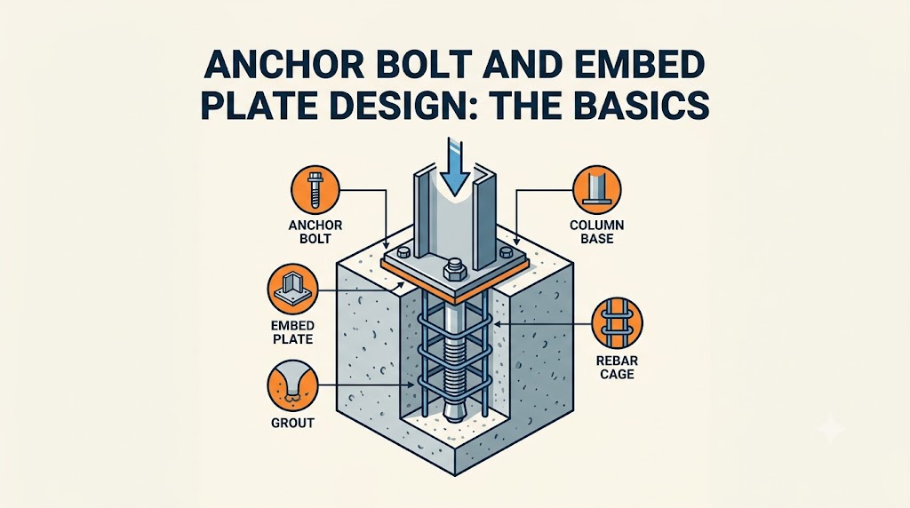
An anchor bolt’s tensile capacity in 25 MPa / 3,600 psi concrete is determined by the lesser of three failure modes: steel fracture, concrete breakout, and pullout from bond. For a standard M20 / 3/4 in cast-in-place anchor bolt with 200 mm / 8 in embedment, the concrete breakout design capacity works out to around 92 kN / 20,700 lbf — which, for this particular size and embedment, comfortably exceeds the bolt’s steel tension limit of around 80 kN / 18,000 lbf, meaning steel fracture governs rather than concrete breakout. That balance shifts with bolt size, as the reference table below shows.
How Anchor Bolt Capacity Is Calculated
The governing standard for anchor design in concrete is ACI 318 Appendix D / Chapter 17 in North America and AS 5216 / EN 1992-4 in Australia and Europe. All use the same Concrete Capacity Design (CCD) method for breakout, which models failure as a cone of concrete pulled out by the anchor.
Concrete breakout capacity in tension (single anchor, no edge effects): Ncb = kc × √f’c × hef^1.5 where kc = 10 (cast-in) or 7 (post-installed), f’c is compressive strength in MPa, and hef is effective embedment depth in mm.
Worked example: M20 cast-in anchor, hef = 200 mm, f’c = 25 MPa:
Ncb = 10 × √25 × 200^1.5 = 10 × 5 × 2,828 = 141,400 N = 141.4 kN / 31,800 lbf
That is the nominal breakout capacity for an isolated anchor with no edge or spacing effects. Apply the strength reduction factor (φ = 0.65 for brittle failures under ACI 318) and you get a design capacity of 91.9 kN / 20,700 lbf — which comfortably exceeds the bolt’s steel fracture limit. In practice, spacing and edge distance modifiers (AN/ANco and ψ-factors) reduce this considerably when anchors are grouped or near concrete edges.
Use the anchor bolt / embed plate calculator to apply all modifier factors simultaneously — it handles edge distance, spacing, eccentricity, and combined tension-shear interaction in a single calculation.
Anchor Bolt Capacity Reference: Common Sizes and Embedments
Design capacities below use ACI 318 Chapter 17, φ = 0.65, kc = 10 (cast-in), f’c = 25 MPa / 3,600 psi, single anchor with no edge effects or spacing reductions. Shear capacity assumes concrete controls and is an estimate. Bold marks whichever of tension breakout or steel tension is the lower, governing value for that bolt size — per the CCD formula above, this is steel for every size shown here except the largest.
| Bolt Size | Embedment (hef) | Design Tension (φNcb) | Steel Tension Limit | Design Shear (est.) |
| M12 / 1/2 in | 125 mm / 4.9 in | 45 kN / 10,200 lbf | 29 kN / 6,520 lbf | 18 kN / 4,050 lbf |
| M16 / 5/8 in | 150 mm / 5.9 in | 60 kN / 13,400 lbf | 52 kN / 11,700 lbf | 28 kN / 6,300 lbf |
| M20 / 3/4 in | 200 mm / 7.9 in | 92 kN / 20,700 lbf | 80 kN / 18,000 lbf | 42 kN / 9,450 lbf |
| M24 / 1 in | 250 mm / 9.8 in | 129 kN / 28,900 lbf | 115 kN / 25,860 lbf | 60 kN / 13,500 lbf |
| M30 / 1-1/4 in | 300 mm / 11.8 in | 169 kN / 38,000 lbf | 181 kN / 40,700 lbf | 88 kN / 19,800 lbf |
Note: where steel strength controls (bold in table), increasing embedment depth alone will not increase capacity — you must upgrade bolt grade or diameter. At the M30 size, concrete breakout becomes the governing case instead, so increasing embedment does help there.
Embed Plate Design: When Bolts Are Not Enough
An embed plate is a steel plate cast into the concrete surface, to which structural elements are later welded or bolted. They are used where: (a) the connection force is too high for bolt groups alone, (b) precise load transfer alignment is required, or (c) the structural element is attached after the concrete is placed and loads must be fully transferred in shear and bending.
Embed plate design involves three checks:
1. Stud or anchor capacity: the headed studs or bolts welded to the back of the plate must resist the full factored load in tension and shear, using the same CCD method as standalone anchors.
2. Plate bending: the plate must be thick enough not to yield in bending between the stud group and the edge of the connected element. Minimum plate thickness is typically determined by: t ≥ √(6 × M / (Fy × b)), where M is the moment transferred to the plate per unit width, Fy is the plate yield strength (typically 250 MPa / 36 ksi), and b is the plate width.
3. Weld design: fillet welds connecting the structural element to the plate must transfer the design load without throat failure. A 6 mm / 1/4 in fillet weld has a design capacity of approximately 0.84 kN/mm / 4,800 lb/in of weld length.
Headed studs on embed plates are commonly 13 mm / 1/2 in or 19 mm / 3/4 in diameter, spaced at a minimum of 6d (six stud diameters) centre-to-centre to avoid group breakout reductions. Edge distance from plate edge to concrete surface should be at least 6 × stud diameter to prevent concrete spalling at the plate perimeter.
Common Mistakes in Anchor and Embed Plate Design
Ignoring edge distance reductions on grouped anchors. Four anchor bolts at 150 mm / 6 in centres near a concrete edge at 100 mm / 4 in have overlapping breakout cones and a severely reduced group capacity — often 30–50% of the isolated anchor value. Designing each bolt independently and multiplying by four is incorrect and potentially dangerous. Apply all ψ-factors as required by ACI 318 Chapter 17 or the equivalent national standard.
Using post-installed adhesive anchors without verifying sustained load temperature limits. Most epoxy anchors are derated at sustained temperatures above 40°C / 104°F. In rooftop mechanical applications, summer concrete temperatures can reach 60–70°C / 140–158°F. At those temperatures, some adhesive systems lose 50–70% of their rated capacity. Always check the anchor manufacturer’s temperature-load interaction chart, not just the ambient rating.
Specifying cast-in anchors without setting jigs. Position tolerance for cast-in bolts is typically ±3 mm / 1/8 in for column base plates and ±1.5 mm / 1/16 in for machinery anchors. Without a properly braced template bolted to the formwork, anchors move during concrete placement. A misplaced bolt by 20 mm / 3/4 in shifts it into an unintended edge distance zone, reducing capacity without any visual indication after stripping.
Neglecting shear interaction under combined loading. Anchors under combined tension and shear must satisfy a tri-linear or unity check: (Nu/φNn)^5/3 + (Vu/φVn)^5/3 ≤ 1.0 under ACI 318. An anchor designed for 40 kN / 9,000 lbf tension that also carries 25 kN / 5,620 lbf shear may fail at 70% of either individual limit. Designing for tension and shear independently and assuming they add directly is unconservative.
Related Calculators You Might Need
After sizing anchor bolts, you’ll often need to check the concrete section they’re embedded in. The concrete load capacity calculator confirms the footing or pedestal can handle the transferred forces. For column base applications, the concrete column / pier calculator sizes the concrete element receiving the anchor group. If you’re working out how much concrete the footing or pedestal requires, the concrete footing calculator handles rectangular and circular footings, and the concrete compressive strength converter lets you move between MPa, PSI, and N/mm² when interpreting anchor manufacturer data sheets.
Frequently Asked Questions
What is the minimum embedment depth for anchor bolts in concrete?
Under ACI 318, minimum effective embedment depth (hef) for cast-in anchors is 8 times the bolt diameter (8d). For a 20 mm / 3/4 in bolt, that is 160 mm / 6.3 in minimum. Post-installed mechanical anchors typically require 4–6d, and adhesive anchors 8–12d depending on the system. These are code minimums — design embedment is usually deeper because concrete breakout often governs before steel strength is reached.
How many anchor bolts do I need for a steel column base plate?
A minimum of four anchor bolts is standard practice for any structural steel column, even where calculation shows two would suffice in pure compression. Four bolts provide stability during erection, handle accidental eccentricity, and resist any tension from uplift or lateral forces. For moment-resisting base plates or seismic zones, six to eight bolts in two rows are common. The bolt group is sized to resist the full factored base shear and any overturning tension on the windward bolt row.
Cast-in vs post-installed anchors: which is stronger?
Cast-in headed anchors (hooked or headed bolts) achieve a kc factor of 10 in the breakout calculation. Post-installed mechanical anchors use kc = 7, giving roughly 30% less breakout capacity at the same embedment. Adhesive post-installed anchors can approach cast-in performance if correctly installed and within temperature limits, but require a more complex design including adhesive bond strength checks. Cast-in anchors are preferred wherever the bolt layout is known at time of pour.
What plate thickness should I use for a structural embed plate?
For headed-stud embed plates in residential and light commercial construction, 12 mm / 1/2 in plate thickness is a common minimum. Heavily loaded industrial embeds may require 20–25 mm / 3/4–1 in plate. The required thickness is calculated from the bending moment transferred to the plate between the stud group and the edge of the attached element — not a rule of thumb. Undersized plates yield locally, shifting load to the outer studs and causing premature stud fracture.
Do I need special anchors for seismic zones?
Yes. In seismic design categories C through F under IBC / ASCE 7, anchors in the seismic load path must be designed for ductile behaviour — either the steel controls failure (not concrete breakout) or the anchor group is designed for the amplified seismic force with overstrength factor Ωo. This requirement often drives larger bolt diameters, deeper embedment to push capacity into the steel-governed regime, and prohibition of certain post-installed anchor types. Check the structural calculators for tools covering seismic load combinations.