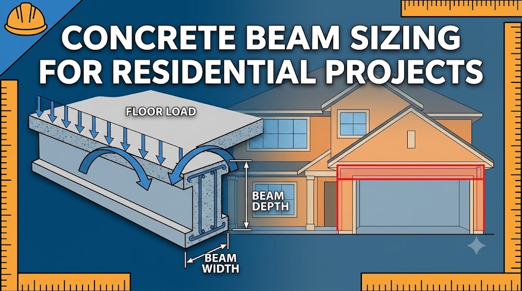
For a first estimate, make a residential concrete beam about one-tenth to one-twelfth of its span deep and 250–300 mm / 10–12 in wide. A 4 m / 13 ft beam lands at roughly 350–400 mm / 14–16 in. That starting size then has to pass three checks: bending, shear and deflection. Depth does most of the work in all three, which is why getting it wrong by even 50 mm / 2 in shows up later as cracked finishes, a sagging soffit or an expensive retrofit.
Key numbers at a glance
- Starting depth: span ÷ 10 to span ÷ 12 for a simply supported beam.
- Code floor (ACI 318): span ÷ 16 simply supported, span ÷ 21 with both ends continuous.
- Design moment: M = wL² ÷ 8 for a simply supported beam under uniform load.
- Stirrups: spaced no further apart than half the beam’s effective depth.
- Deflection: L/360 under live load, tightening to L/480 where partitions or brittle finishes sit on the beam.
- Sign-off: any beam carrying a floor, wall or roof needs a design by a licensed structural engineer.
On this page: Depth rule and code minimum · Sizing in five steps · Span and load table · What changes the depth · Deflection limits · Common mistakes · Pouring and propping · FAQ
How Deep Should a Concrete Beam Be? Rule of Thumb vs Code Minimum
There are two numbers worth knowing before you calculate anything. The first is the designer’s rule of thumb, span ÷ 10 to span ÷ 12, which gives a beam with comfortable reserves of strength and stiffness under normal residential floor loads of 1.5–2.0 kPa / 30–40 psf. The second is the minimum overall depth in ACI 318, below which you are required to calculate deflection instead of assuming it will be acceptable.
| Support condition | ACI 318 minimum depth | On a 4 m / 13.1 ft span |
|---|---|---|
| Simply supported | span ÷ 16 | 250 mm / 9.8 in |
| One end continuous | span ÷ 18.5 | 216 mm / 8.5 in |
| Both ends continuous | span ÷ 21 | 190 mm / 7.5 in |
| Cantilever | span ÷ 8 | 500 mm / 19.7 in |
Minimum overall beam depth from ACI 318-19 Table 9.3.1.1, for normal-weight concrete and Grade 60 / 420 MPa reinforcement.
Read that table carefully, because it is easy to misuse. It applies only to beams that do not support partitions or finishes likely to be damaged by deflection. It is a deflection shortcut, not a strength design, so a beam at the minimum depth still needs its bending and shear checked. And for stronger steel the values go up: ACI multiplies them by (0.4 + fy ÷ 700), which is about 1.11 for the Grade 500 bars common outside North America.
In practice most house beams end up well above the code floor, somewhere near the rule of thumb, because extra depth is the cheapest way to cut both steel and sag.
How to Size a Concrete Beam: The Core Formula in Five Steps
The example below follows one beam from load to reinforcement: a 5 m / 16.4 ft simply supported beam, 250 mm / 10 in wide, carrying a 120 mm / 4.75 in slab with beams spaced 2 m / 6.6 ft apart. Concrete is 25 MPa / 3,600 psi and steel is Grade 60 / 420 MPa.
Step 1: Add up the load on the beam
The load per metre of beam, w, is the floor load multiplied by the width of floor the beam supports (its tributary width), plus the beam’s own weight. Reinforced concrete weighs about 24 kN/m³ / 150 lb/ft³.
- Slab: 0.12 m × 24 = 2.88 kPa, plus 1.0 kPa of finishes = 3.88 kPa. Over a 2 m width that is 7.76 kN/m.
- Beam stem below the slab: 0.25 m × 0.30 m × 24 = 1.80 kN/m.
- Dead load (D): 7.76 + 1.80 = 9.56 kN/m.
- Live load (L): 2.0 kPa × 2 m = 4.0 kN/m.
- Factored load: 1.2D + 1.6L = 1.2 × 9.56 + 1.6 × 4.0 = 17.9 kN/m, say 18 kN/m / 1,233 lb/ft.
The 1.2 and 1.6 are the ACI and ASCE 7 load factors. Eurocode uses 1.35 and 1.5, which gives 18.9 kN/m for the same beam. If you want to cross-check what the slab itself is carrying, the guide to how much weight a concrete slab can hold covers the floor side of the calculation.
Step 2: Pick a trial size
Span ÷ 12 gives 5,000 ÷ 12 = 417 mm, so try 250 × 420 mm / 10 × 16.5 in overall. That is comfortably above the ACI minimum of span ÷ 16 = 313 mm / 12.3 in.
Step 3: Calculate the design moment
M = (w × L²) ÷ 8, where M is the design moment, w is the factored uniform load per metre or foot of beam, and L is the span.
M = (18 × 5²) ÷ 8 = 56.25 kN·m / 41.5 kip·ft
Step 4: Find the bottom steel
Effective depth d is measured from the top of the beam to the centre of the bottom bars: 420 − 40 cover − 10 stirrup − 8 (half a 16 mm bar) = 362 mm / 14.25 in. A quick estimate of the steel area is:
As ≈ M ÷ (0.9 × fy × 0.9d) = 56,250,000 ÷ (0.9 × 420 × 0.9 × 362) = 457 mm² / 0.71 in²
The exact ACI stress-block solution gives 431 mm², so the shortcut errs slightly on the safe side. Three 16 mm bars (603 mm²) or three #5 bars (0.93 in²) cover it with margin. Once the bar count is settled, the rebar calculator turns it into total length and weight for ordering.
Step 5: Check shear and deflection
Shear is highest at the supports: V = wL ÷ 2 = 45 kN / 10.1 kip, dropping to about 38.5 kN / 8.7 kip at the critical section one effective depth out from the support face. The concrete alone resists roughly 58 kN / 13 kip here, so shear demand is covered and the minimum stirrup rule governs: 10 mm / #3 closed stirrups at no more than d ÷ 2, which is 181 mm, so use 175 mm / 7 in centres.
For deflection, 420 mm exceeds the span ÷ 16 minimum, so ACI does not require a calculation unless the beam carries partitions or brittle finishes. If it does, see the deflection limits below.
With the section fixed, the concrete beam calculator gives the concrete volume and wet weight for rectangular and T-beams, which is what you need for ordering and for sizing the props.
Beam Sizing by Span and Load: Residential Reference Table
The table below runs the same five steps for the most common residential spans. Beam width is 250 mm / 10 in throughout. The load column is the factored load and must already include the beam’s own weight.
| Span | Factored load and design moment | Overall depth and bottom steel |
|---|---|---|
| 3.0 m / 9.8 ft | 12 kN/m (822 lb/ft) 13.5 kN·m (10.0 kip·ft) | 280 mm / 11 in deep 2 × 12 mm or 2 × #4 |
| 4.0 m / 13.1 ft | 15 kN/m (1,028 lb/ft) 30.0 kN·m (22.1 kip·ft) | 350 mm / 14 in deep 2 × 16 mm or 2 × #5 |
| 5.0 m / 16.4 ft | 18 kN/m (1,233 lb/ft) 56.3 kN·m (41.5 kip·ft) | 420 mm / 16.5 in deep 3 × 16 mm or 3 × #5 |
| 6.0 m / 19.7 ft | 20 kN/m (1,370 lb/ft) 90.0 kN·m (66.4 kip·ft) | 500 mm / 19.7 in deep 3 × 20 mm or 3 × #6 |
| 7.5 m / 24.6 ft | 22 kN/m (1,507 lb/ft) 154.7 kN·m (114.1 kip·ft) | 600 mm / 23.6 in deep 3 × 20 mm or 3 × #7 |
Preliminary sizes for simply supported rectangular beams, 250 mm / 10 in wide. Required steel areas, row by row: 187, 283, 431, 570 and 805 mm², calculated to ACI 318 strength design with φ = 0.9. For orientation only; not a substitute for an engineer’s design.
Assumptions behind the table: f’c = 25 MPa / 3,600 psi concrete, Grade 60 / 420 MPa reinforcement, 40 mm / 1.5 in clear cover, 10 mm / #3 stirrups, and bars in a single layer. The 3 m row is governed by ACI’s minimum reinforcement, not by the moment. At these loads the concrete carries the shear on its own in every row, so stirrups go in at the maximum permitted spacing of half the effective depth.
One caution on steel grade. Grade 500 (B500) bar used across Europe, the UK and much of Asia is a stronger steel than Grade 60, not a unit conversion of it. Fewer or smaller bars may work, but the steel area has to be recalculated; never swap one grade for the other by eye. If your drawings mix unit systems, the PSI to MPa converter and the imperial to metric converter keep the numbers straight.
Continuous beams, built into supports and running over more than one span, can be shallower: the ACI minimum drops from span ÷ 16 to span ÷ 18.5 or span ÷ 21, roughly 15–25% less depth. The trade-off is top steel over the supports, covered in the next section.
What Affects Beam Depth in Practice
Depth beats width, every time
Stiffness rises with the cube of depth but only in direct proportion to width. Making a beam 20% deeper makes it about 73% stiffer; making it 20% wider makes it 20% stiffer for the same extra concrete. Width still has a job to do, though. It has to fit the bars with at least 25 mm / 1 in of clear space between them (and never less than one bar diameter), and it should suit the wall or column the beam sits on. In a 250 mm web with 40 mm cover, three 20 mm bars fit in one layer; four do not.
Concrete strength matters less than you would expect
It is a common belief that stronger concrete means much less steel. For an ordinary under-reinforced beam it does not. Running the 5 m example again with 32 MPa / 4,600 psi concrete instead of 25 MPa cuts the bottom steel from 431 mm² to 427 mm², about 1%. The bending capacity is controlled by the steel and the depth, not the concrete.
Where the stronger mix does earn its cost is in shear capacity and stiffness (both rise by around 13% for that step up, because they follow the square root of strength) and above all in durability. Our guide to concrete grades explains what each strength class is meant for, and the compressive strength converter converts strength values between PSI, MPa and kgf/cm².
Cover requirements
Cover is the concrete between the outside of the stirrup and the beam face, and every millimetre of it comes off the effective depth. ACI 318 sets these minimums for cast-in-place beams:
- Interior, not exposed to weather: 40 mm / 1.5 in.
- Exposed to weather or in contact with ground: 40 mm / 1.5 in for #5 (16 mm) bars and smaller, 50 mm / 2 in for #6 (19 mm) and larger.
- Cast directly against soil: 75 mm / 3 in.
Eurocode 2 works differently, setting cover by exposure class and design life, so interior values can be lower and coastal values higher. Use the figure on your drawings, and hold it with proper bar chairs or spacers during the pour.
Support conditions
A simply supported beam, free to rotate at each end, has its largest moment at midspan and needs its main steel at the bottom. A continuous beam shares that moment with its supports: the midspan moment drops, but a reversed (hogging) moment appears over each support, putting the top of the beam in tension there. That zone needs top bars, properly lapped and anchored. Leaving them out, or stopping them short, is a classic detailing error, because the beam looks finished and only cracks over the supports once it is loaded.
The slab helps: T-beam action
When the beam and slab are poured together, part of the slab acts as a wide top flange and the pair behaves as a T-beam. That raises midspan capacity and stiffness considerably compared with the bare rectangular stem. It is also why a monolithic pour is preferred over casting the beam first and the slab later. The slab thickness guide and the slab thickness selector help you settle the flange thickness first.
Torsion
Torsion rarely matters for a straight beam loaded evenly from both sides. It becomes important for edge (spandrel) beams with slab on one side only, beams supporting cantilevered balconies, and beams at the corners of L-shaped plans. These need a separate torsion check and closed stirrups with extra longitudinal bars, which is firmly engineer territory.
Deflection Limits: L/360, L/480 and What They Actually Mean
L/360 is the best-known number in beam design, but it is one of several limits and it applies to one specific thing: the immediate sag caused by live load alone. Which limit governs depends on what the beam is holding up.
| Limit | What it applies to | On a 5 m / 16.4 ft span |
|---|---|---|
| L/360 (ACI 318) | Immediate deflection from live load, on floors with nothing fragile attached | 13.9 mm / 0.55 in |
| L/480 (ACI 318) | Deflection occurring after partitions or finishes likely to be damaged are installed, including long-term creep | 10.4 mm / 0.41 in |
| L/240 (ACI 318) | The same after-installation deflection, where attached elements are not likely to be damaged | 20.8 mm / 0.82 in |
| Span/250 (Eurocode 2) | Total sag under long-term (quasi-permanent) load | 20 mm / 0.79 in |
| Span/500 (Eurocode 2) | Deflection after construction that could damage adjacent parts such as partitions | 10 mm / 0.39 in |
Deflection limits from ACI 318-19 Table 24.2.2 and EN 1992-1-1 clause 7.4.1.
The long-term part is what catches people out. Concrete keeps deflecting under sustained load through creep and shrinkage. ACI estimates the additional long-term deflection by multiplying the immediate deflection from sustained loads by a factor that grows with time: 1.0 at three months, 1.2 at six months, 1.4 at one year and 2.0 at five years or more. So a beam that sags 5 mm under its permanent load on day one can be expected to reach about 15 mm eventually. Compression steel in the top of the beam reduces that factor.
To run the numbers for your own span, use the deflection calculator.
Common Mistakes in Residential Beam Design
1. Forgetting the wall on top. Span tables assume a uniform floor load of 1.5–2.0 kPa / 30–40 psf. A masonry partition sitting on the beam is a separate line load, and often the bigger one. A single-leaf 115 mm / 4.5 in brick wall 3 m / 10 ft high adds roughly 7 kN/m / 470 lb/ft; a 230 mm / 9 in wall adds about 14 kN/m / 950 lb/ft, which is as much as the whole floor load in the 4 m row of the table above. Water tanks, stone worktops and planters need the same treatment.
2. Checking only short-term deflection. A beam that passes L/360 on day one can still crack the plaster or jam a door five years later. Wherever partitions or brittle finishes are involved, the L/480 check with the long-term multiplier is the one that counts.
3. Stirrups spaced too far apart. A flat 300 mm / 12 in spacing is a common site habit, and it breaks the ACI limit on any beam shallower than about 660 mm / 26 in overall. The maximum spacing is half the effective depth (and never more than 600 mm / 24 in), dropping to a quarter of the effective depth where shear is high. Place the first stirrup close to the support face, typically within 50 mm / 2 in. The rebar spacing guide compares the ACI, Eurocode and BS rules, and the rebar spacing calculator works out the layout.
4. Too many bars for the width. Bars crammed together leave no room for concrete to flow around them, which causes honeycombing exactly where the steel needs to bond. If the bars do not fit in one layer with proper clear spacing, widen the beam or deepen it; do not squeeze them.
5. Under-specifying the mix. ACI 318 sets an absolute floor of 17 MPa / 2,500 psi for structural concrete, and most engineers specify 25–32 MPa / 3,600–4,600 psi for house beams. The reason is not bending strength, as shown above, but durability, shear capacity and a margin for site variability. Strength is set largely by the water-cement ratio, which is why water added on site to loosen a stiff mix is so damaging.
6. Replacing bars with fibres or mesh. Fibres and welded wire mesh control cracking in slabs. They do not replace the main bars and stirrups in a beam. See fiber reinforcement vs rebar for where each belongs.
Pouring, Propping and Stripping the Beam
A correctly sized beam can still be spoiled in its first three weeks. Three practical points:
The volume is small, so plan the delivery. The 5 m example beam is only 0.53 m³ / 0.69 yd³ of concrete, far below a full truck. Pour it together with the slab where you can, or expect a short-load fee on a part load.
Props carry the wet weight. That same beam weighs about 1,260 kg / 2,780 lb before it has any strength of its own, and the slab around it adds far more. The concrete weight calculator gives the figure for your section.
Leave the soffit props in long enough. Where the engineer has not specified a stripping strength, the guidance in ACI 347 for beam soffits is 7 days for clear spans under 3 m / 10 ft, 14 days for 3–6 m / 10–20 ft and 21 days for longer spans. Those figures assume air temperatures above 10°C / 50°F and a design live load smaller than the dead load, which is typical for houses. Strength, not the calendar, is the real test, and cold weather stretches every one of those periods. Side forms can come off much earlier. More detail is in how long concrete takes to cure, and the curing time estimator adjusts for temperature.
When you need a structural engineer
Use this guide to understand a design, sanity-check a drawing or budget a job. Do not build from it. A licensed engineer’s design is required, and usually a permit too, for any beam that carries a floor, roof or wall, spans more than about 3 m / 10 ft, replaces a load-bearing wall, supports a cantilever, or sits in a seismic or high-wind region. The sizes here assume simple gravity loading and none of those complications.
Related Calculators You Might Need
- Concrete beam calculator: volume, weight and material cost for rectangular and T-beams.
- Rebar calculator: total length and weight of reinforcing steel for ordering.
- Rebar spacing calculator: bar and stirrup layout.
- Concrete load capacity calculator: a cross-check on what the supported slab is carrying.
- Concrete column and pier calculator: for the supports the beam frames into.
- Anchor bolt and embed plate calculator: for fixing steel or timber to the finished beam, with the design basics here.
Frequently Asked Questions
How deep does a concrete beam need to be for a 4 m span?
For a factored load of 15 kN/m / 1,028 lb/ft, a simply supported 4 m / 13.1 ft beam works at about 350 mm / 14 in deep and 250 mm / 10 in wide with 25 MPa concrete and two 16 mm (#5) bottom bars. The ACI code minimum for that span is 250 mm / 9.8 in, or 190 mm / 7.5 in if both ends are continuous, but shallower beams need more steel and a calculated deflection check. Treat all of these as starting values for an engineer to confirm.
Is it better to make a concrete beam deeper or wider?
Deeper. Stiffness increases with the cube of the depth and only linearly with width, so 20% more depth gives about 73% more stiffness, against 20% for the same increase in width. Widen a beam when the bars will not fit in one layer or when it needs to match the wall or column below.
What concrete strength is best for residential beams?
25 MPa / 3,600 psi is a sensible working minimum for house beams, and 28–32 MPa / 4,000–4,600 psi is common on longer spans or exposed work. ACI 318’s absolute minimum for structural concrete is 17 MPa / 2,500 psi. Higher strength adds durability and shear capacity but barely changes the amount of bending steel, so do not expect it to shrink the beam. The engineer’s specified strength on the drawings always governs. For mix proportions by grade, see concrete mix ratios from M10 to M40.
Do I need stirrups in a small residential beam?
Yes. Stirrups resist shear, hold the main bars in position during the pour and stop a sudden diagonal-cracking failure. For a typical house beam, 10 mm / #3 closed stirrups at a spacing no greater than half the effective depth is the baseline: about 140 mm / 5.5 in centres for a 350 mm / 14 in deep beam and 175 mm / 7 in for a 420 mm / 16.5 in beam. Spacing tightens near the supports when shear is high.
What’s the difference between a drop beam and a hidden beam?
A drop beam hangs below the slab soffit and uses that extra depth efficiently. A hidden (flush or concealed) beam is a heavily reinforced strip within the slab thickness, so its depth is only the slab depth. That makes it flexible: by the ACI minimum-depth ratios, a 150 mm / 6 in slab strip suits spans of only about 2.4 m / 8 ft simply supported, or 3.15 m / 10 ft with both ends continuous, before deflection has to be calculated. Hidden beams need much more steel and are best kept to short spans and light loads.
Can I use bagged concrete for a structural beam?
Only for small members such as short lintels of about 1.5 m / 5 ft or less, and only with the water measured for every batch. The problem is not the product but consistency: dozens of hand-mixed batches vary in water content, and each joint between batches is a potential weak plane. Anything longer or more heavily loaded should be plant-batched ready-mix with a delivery ticket stating the strength. Bags vs ready-mix concrete covers the trade-offs, and the ready-mix vs bagged cost calculator compares the price once you know the beam volume.
How long should props stay under a concrete beam?
Until the concrete has reached the stripping strength the engineer specifies. Where none is given, ACI 347 guidance for beam soffits is 7 days for spans under 3 m / 10 ft, 14 days for 3–6 m / 10–20 ft and 21 days above that, in temperatures over 10°C / 50°F. Allow longer in cold weather; our cold-weather concreting guide explains why.
References and Standards
- American Concrete Institute, ACI 318 Building Code Requirements for Structural Concrete: Table 9.3.1.1 (minimum beam depth), Table 19.2.1.1 (minimum strength), Table 20.5.1.3.1 (cover), Section 9.7.6.2 (stirrup spacing) and Table 24.2.2 (deflection limits). Table numbers follow the 2019 edition; ACI CODE-318-25 is the current edition, so check which one your jurisdiction has adopted.
- American Concrete Institute, technical FAQ on concrete cover for reinforcement.
- European Commission Joint Research Centre, EN 1992 Eurocode 2: Design of concrete structures: Part 1-1, clause 7.4.1 (deflection limits).
- International Code Council, 2024 International Residential Code, Chapter 3: Table R301.5 (minimum residential live loads of 30 psf for sleeping rooms and 40 psf elsewhere).
- American Concrete Institute, ACI 347R, Guide to Formwork for Concrete (form and shore removal times).
How we check our figures is set out in our editorial policy.